H bridge driving device of automobile electric boosting steering motor

A technology of electric power steering and driving device, which is applied in the direction of electric steering mechanism, motor generator/starter, single DC motor starter, etc., and can solve the problem of controller function failure, occupying installation space, and large armature current of EPS motor and other issues to achieve high integration and reliability, reduce cycle time and complexity, and improve drive efficiency

Inactive Publication Date: 2008-12-31
JIANGSU UNIV
View PDF0 Cites 13 Cited by
  • Summary
  • Abstract
  • Description
  • Claims
  • Application Information

AI Technical Summary

Problems solved by technology

For method 1, there is no need for an upper bridge booster circuit, and the advantages are convenient and simple to drive. However, due to the large on-resistance of the P-channel MOS transistor and the large current of the armature of the EPS motor, the distribution voltage of the MOS transistor on-resistance is too high. Large size, insufficient H-bridge drive voltage, severe heat generation of MOS tubes, etc., as well as the disadvantages of complex manufacturing process and high price, this method is generally not used in the motor drive of automobile electric power steering system
For the second method, discrete analog components are usually used to form the H-bridge drive circuit, and each arm of the H-bridge only uses a MOS tube. The disadvantage of this method is: the combination of discrete components increases the controller circuit. The area of ​​the board occupies the installation space, increases the cost of the controller, and more seriously reduces the anti-interference ability of the controller; since each arm of the H-bridge only uses one MOS tube, when a certain MOS breaks down or other When it fails due to a fault, it will inevitably lead to the failure of the entire controller function, and the replacement of the MOS tube is a complex temporary repair behavior.

Method used


Image

  • H bridge driving device of automobile electric boosting steering motor
  • H bridge driving device of automobile electric boosting steering motor
  • H bridge driving device of automobile electric boosting steering motor

Examples


Embodiment Construction

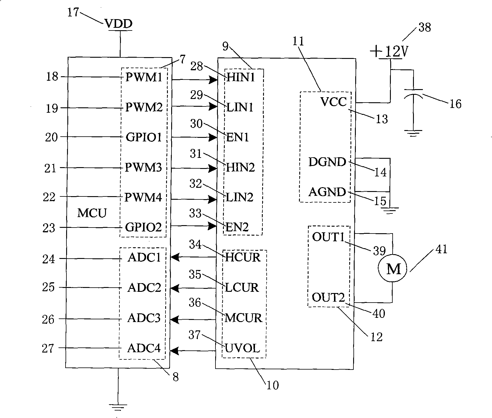
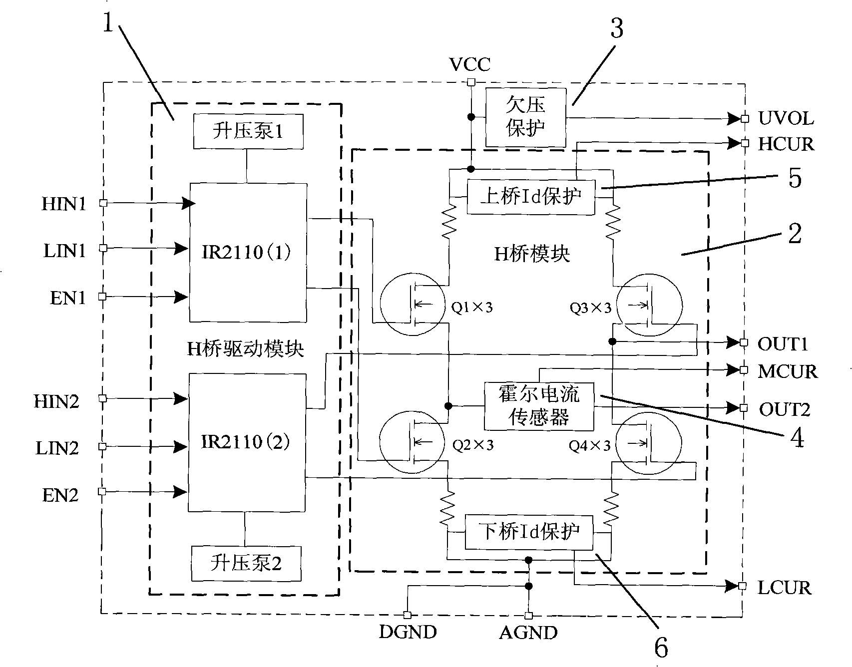
[0014] like figure 1 , 2 As shown, the H-bridge drive module 1 is connected to the H-bridge module 2, the undervoltage protection module 3 is connected to the H-bridge module 2, and the H-bridge module 2 includes a motor armature current feedback module 4, and a MOS tube upper bridge drain current monitoring and protection module 5 and MOS transistor lower bridge drain current monitoring and protection module 6 . The microprocessor pulse width modulation PWM register, the general input and output port GPIO 7 and the microprocessor analog-to-digital conversion register ADC 8 are respectively connected to the control terminal group 9 and the monitoring protection terminal group 10 of the H-bridge driving module 1 . The present invention also includes the power supply terminal group 11 and the motor connection terminal group 12 of the H-bridge driving module 1 . The above-mentioned microprocessor drives the four bridge arms of the H bridge respectively through its own integrate...


PUM


Abstract

The invention discloses an H-bridge drive device of an electric power steering motor of an auto. The device comprises an H-bridge drive module, an H-bridge module, an undervoltage protection module, a motor armature current feedback module, an MOS tube on-bridge drain current monitoring and protecting module and an MOS tube down-bridge drain-electrode current monitoring and protecting module; each arm of the H-bridge module adopts the structure of the parallel connection of three N-channel MOS tubes; the drain electrodes of the three N-channel MOS tubes are connected together, the source electrodes are connected together, and the grid electrodes are connected together after being respectively connected with a resistor in series; the device reduces the power loss of the MOS tubes, enhances the drive efficiency of the H bridge and the reliability of the system, and can effectively avoid the influences of the emergency switching of the motor, the abrupt increase of the pulse current of the MOS tubes, and the abrupt change of armature current of the motor due to the special working conditions such as emergency large turning of an electric power steering system on the steering system, thus having high integration degree, good reliability, convenient use and being applicable to the requirement of safety, energy-saving and environment protection of the auto industry.

Description

technical field [0001] The invention relates to an H-bridge driving device of an automobile electric power steering motor with functions such as MOS tube drain current protection, motor undervoltage protection and motor current feedback, and is suitable for power driving of a direct current motor of an automobile electric power steering system. Background technique [0002] With the development of microelectronics technology and people's increasing requirements for vehicle handling stability, safety, environmental protection, and energy saving, automotive electric power steering systems have become the focus of development in the world's auto parts industry, and are the development direction of modern automotive steering systems. . Automobile electric power steering system is based on the mechanical steering system, according to the torque signal and vehicle speed signal acting on the steering wheel, through the electronic control device, the motor generates an auxiliary for...

Claims


Application Information

Patent Timeline
Patent Type & Authority Applications(China)
IPC IPC(8): H02P1/22H02H7/08H02H7/09H03K17/08B62D5/04
CPCY02P80/10
Inventor 赵景波陈龙刘海妹江浩斌
Owner JIANGSU UNIV
Why Eureka
Try Eureka