Pulse knock rotor spindle engine

A technology of pulse detonation and engine, which is applied in the direction of engine components, engine cooling, machine/engine, etc. It can solve the problems of large noise and single use, and achieve the effect of wide application and overcoming huge noise

Inactive Publication Date: 2009-01-07
RUGAO HUAYANG ALUMINUM PROD
View PDF0 Cites 20 Cited by
  • Summary
  • Abstract
  • Description
  • Claims
  • Application Information

AI Technical Summary

Problems solved by technology

The disadvantage of the pulse detonation engine is that it has single purpose and high noise. At present, it can only be used in the flight system in the form of jet propulsion. There is no new type that can convert its propulsion energy into output energy in the form of output torque from the output shaft. shaft engine emerges

Method used


Image

  • Pulse knock rotor spindle engine
  • Pulse knock rotor spindle engine
  • Pulse knock rotor spindle engine

Examples


Embodiment 1

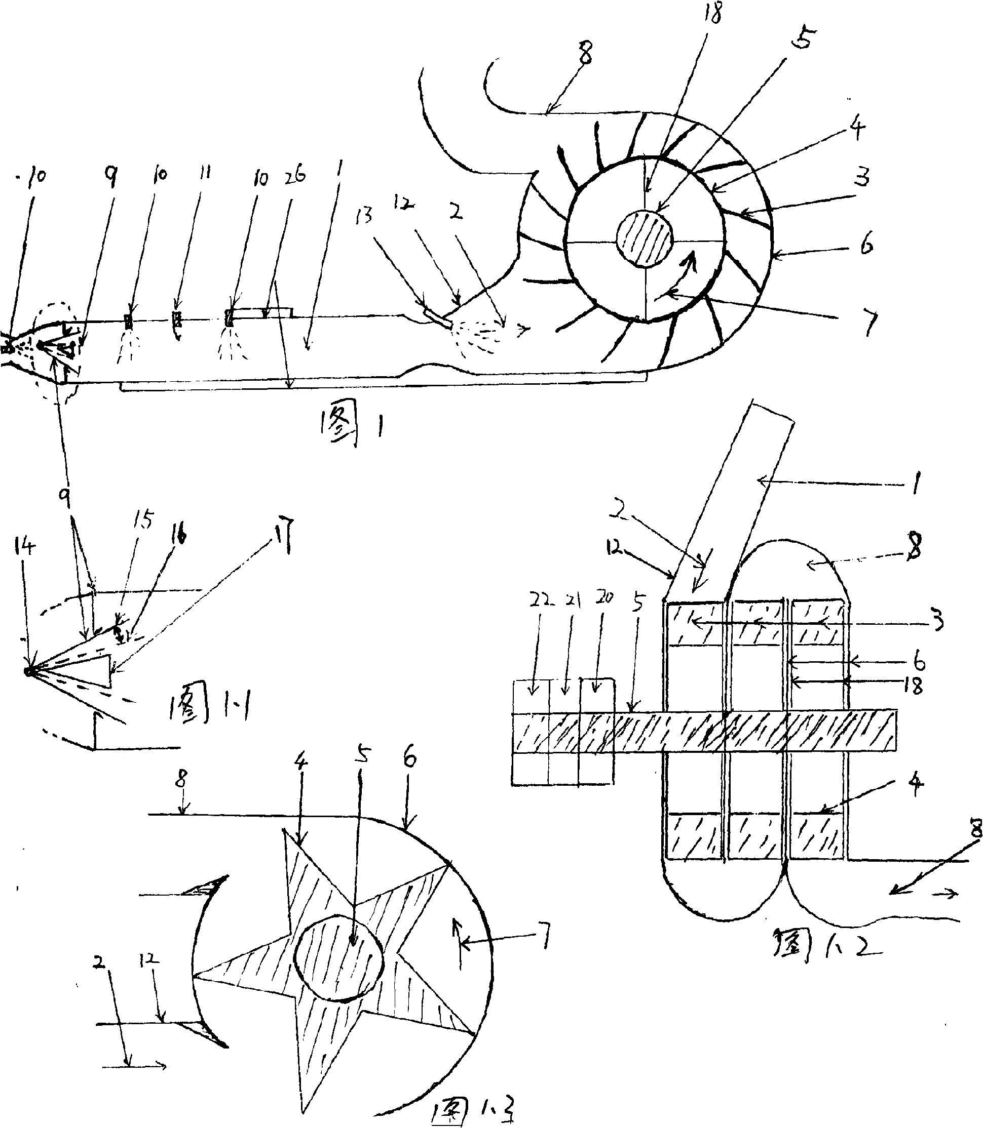
[0033] Embodiment 1: a pulse detonation rotor shaft engine with only one pulse detonation engine: (such as accompanying drawing 1, accompanying drawing 1.2) is mainly driven by a pulse detonation engine 1 with an intake valve 9 and a three-stage impeller rotor 4 An output shaft 5 and other components, the working process is that the air in the pulse detonation engine 1 is mixed with the fuel injected by the fuel nozzle 10, the igniter 11 ignites the pulse detonation engine 1 to work, and the propellant gas 2 generated passes through the propellant gas ejection port 12 Completely enter the casing 6 connected with it, there is a water nozzle 13 in the propelling gas ejection port 12, and the sprayed atomized water can absorb the heat energy in the high-temperature and high-pressure propelling gas 2 and turn it into water vapor to increase the propelling gas 2, the rest of the water can continue to evaporate in the casing 6 to cool down the engine, and the boosted propellant gas 2...

Embodiment 2

[0034] Embodiment 2: a kind of pulse detonation rotary shaft engine that uses hydrogen and oxygen work completely: (as accompanying drawing 1) original structure in the specific embodiment 1 is unchanged, just makes the pulse detonation engine 1 on its basis The upstream of the intake valve 9 is airtightly connected (not shown) with the hydrogen supply pipe, the gas supply regulation system, and the hydrogen cylinder, and the upstream of the nozzle 10 is airtightly connected (not shown) with the oxygen supply pipe, the gas supply regulation system, and the oxygen cylinder. And make the hydrogen / oxygen=2 / 1 (molar ratio) that enters the pulse detonation engine 1 by the gas supply regulating system, all the other work processes are identical with the concrete embodiment 1. Make pulse detonation engine 1 become the pulse detonation rocket engine (PDRE) that uses hydrogen, oxygen fuel by air-breathing pulse detonation engine (PDE) like this, make pulse detonation rotorshaft engine o...

Embodiment 3

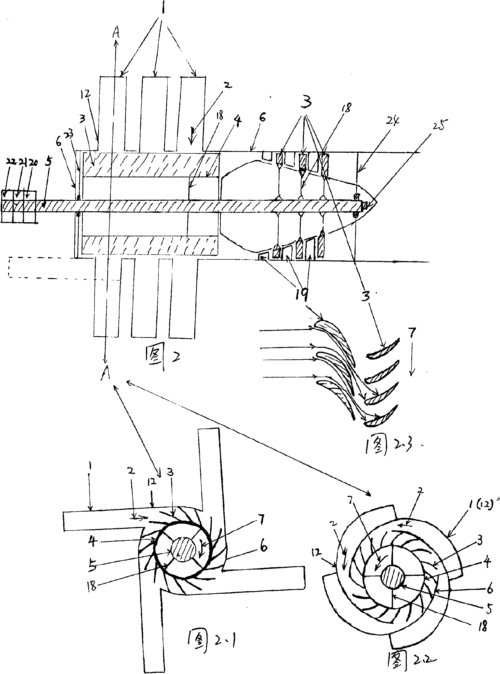
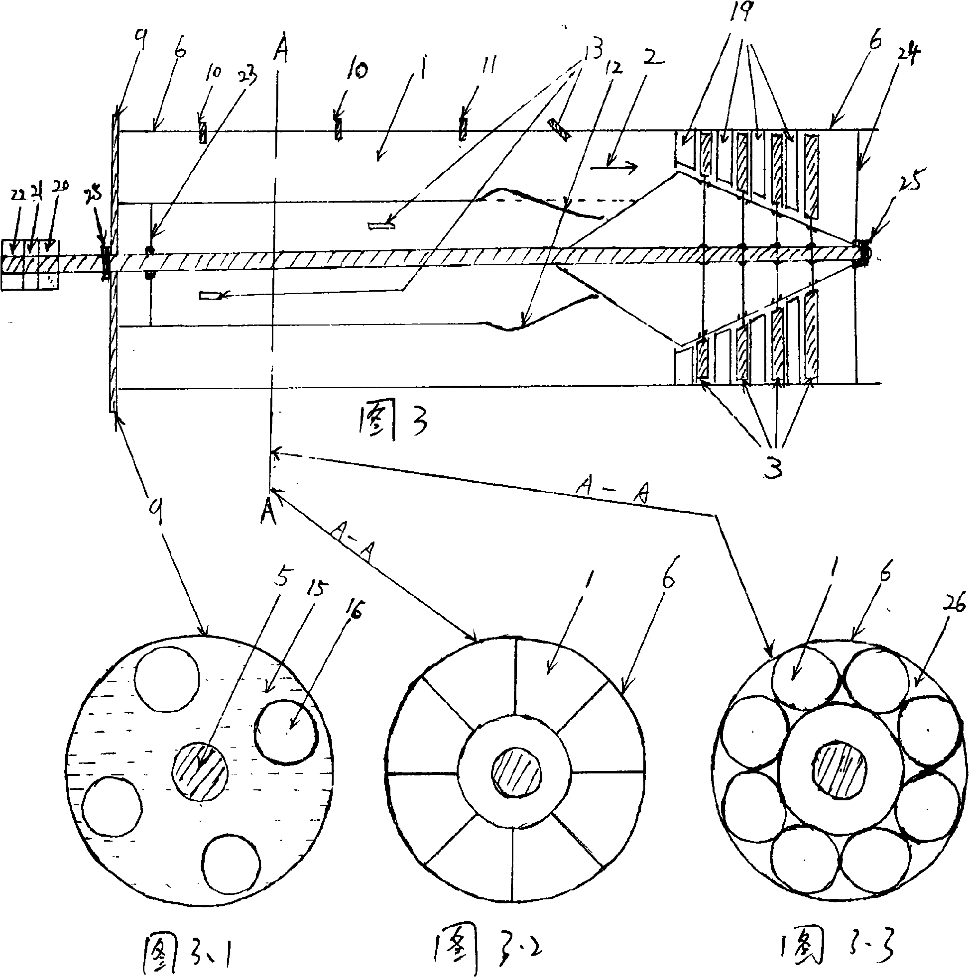
[0035] Embodiment 3: (as accompanying drawing 2) the impeller that is driven by a plurality of pulse detonation engines, turbine composite rotor type pulse detonation rotor shaft engine: its work process is that 12 intake valve type pulse detonation engines 1 work hours The generated propellant gas 2 enters the same engine housing 6 connected to it through each propellant gas outlet 12 after being boosted by water spraying, and jointly tangentially pushes the impeller blades 3 to rotate the impeller rotor 4 and drive the output shaft 5 to rotate At this time, the direction of the propelling gas 2 has been changed by the impeller blades 3, and then the turbine blades 3 of the downstream turbine rotor 4 are pushed again to make the turbine rotor 4 rotate. The front of the turbine blades 3 of each stage of turbine rotor 4 is fixed on the inner wall of the casing 6 The air-guiding stator blade 19 on the top has a total of 1-stage impeller rotor and 3-stage turbine rotor in this fig...


PUM


Abstract

The present invention relates to a pulse detonation rotor shaft engine. In the technical proposal, the pulse detonation rotor shaft engine mainly consists of a pulse detonation engine, a rotor and an output shaft; propulsive gas with the high temperature and high pressure expansion of pulse which is ejected when the pulse detonation engine works is used as a power source to push the rotor to rotate; the rotor drives the output shaft to rotate; a pulse detonation rotor shaft engine uses the output shaft to output most energy produced by the pulse detonation engine by outputting torsion continuously; the output shaft drives various kinds of loads to work. The pulse detonation rotor shaft engine has the beneficial effects as follows: firstly, the pulse detonation rotor shaft engine can be used as a shaft engine to be widely applied in various kinds of dynamic systems, such as ship, submarine, tank, tractor, automobile, train, and the like and has wide purposes; secondly, the pulse detonation rotor shaft engine overcomes the disadvantage of the large noise of the prior pulse detonation engine; thirdly, compared with a piston type engine, the pulse detonation rotor shaft engine has the obvious advantages of simple structure, low cost, high reliability, long service life, light weight, less fraction resistance loss, etc.

Description

1. Technical field: [0001] The invention relates to an engine, in particular to a new-concept pulse detonation rotor shaft engine. 2. Background technology: [0002] At present, the engines that have been widely used to generate high-temperature and high-pressure gas after fuel combustion as the power source, and output most of the power through the output shaft in the form of output torque mainly include reciprocating piston internal combustion engines and gas turbines. Reciprocating piston internal combustion engine: Its normal operation must rely on the precision machining sealing fit between the piston and the cylinder liner. The friction loss between the piston and the cylinder liner is large, and it has extremely high requirements for lubrication and cooling. Once the sealing performance is worn If it is lowered, the pollution will increase, the output power will decrease, and the service life will be short; once the cooling is not good, there will be lockup; the trans...

Claims


Application Information

Patent Timeline
Patent Type & Authority Applications(China)
IPC IPC(8): F02C7/36F02C3/28F02C3/30F02C7/12
Inventor 周林周天宇
Owner RUGAO HUAYANG ALUMINUM PROD
Why Eureka
Try Eureka