ITO test board and test method
A test method and test board technology, applied in the field of LCD manufacturing, can solve problems such as inaccuracy and inconvenient evaluation of ITO glass corrosion, and achieve the effects of improving anti-corrosion ability, ensuring the quality of LCD products, and improving anti-corrosion ability.
- Summary
- Abstract
- Description
- Claims
- Application Information
AI Technical Summary
Problems solved by technology
Method used
Image
Examples
Embodiment 1
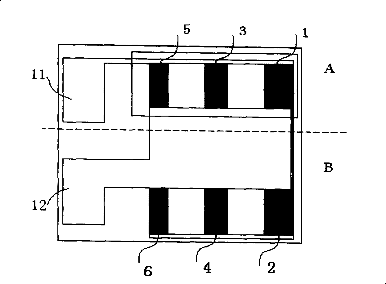
[0022] like figure 1 As shown, the ITO test board includes a glass substrate, an ITO conductive layer, and an insulating layer. The ITO conductive layer is coated on the glass substrate, and the insulating layer is coated on a part of the surface of the ITO conductive layer.
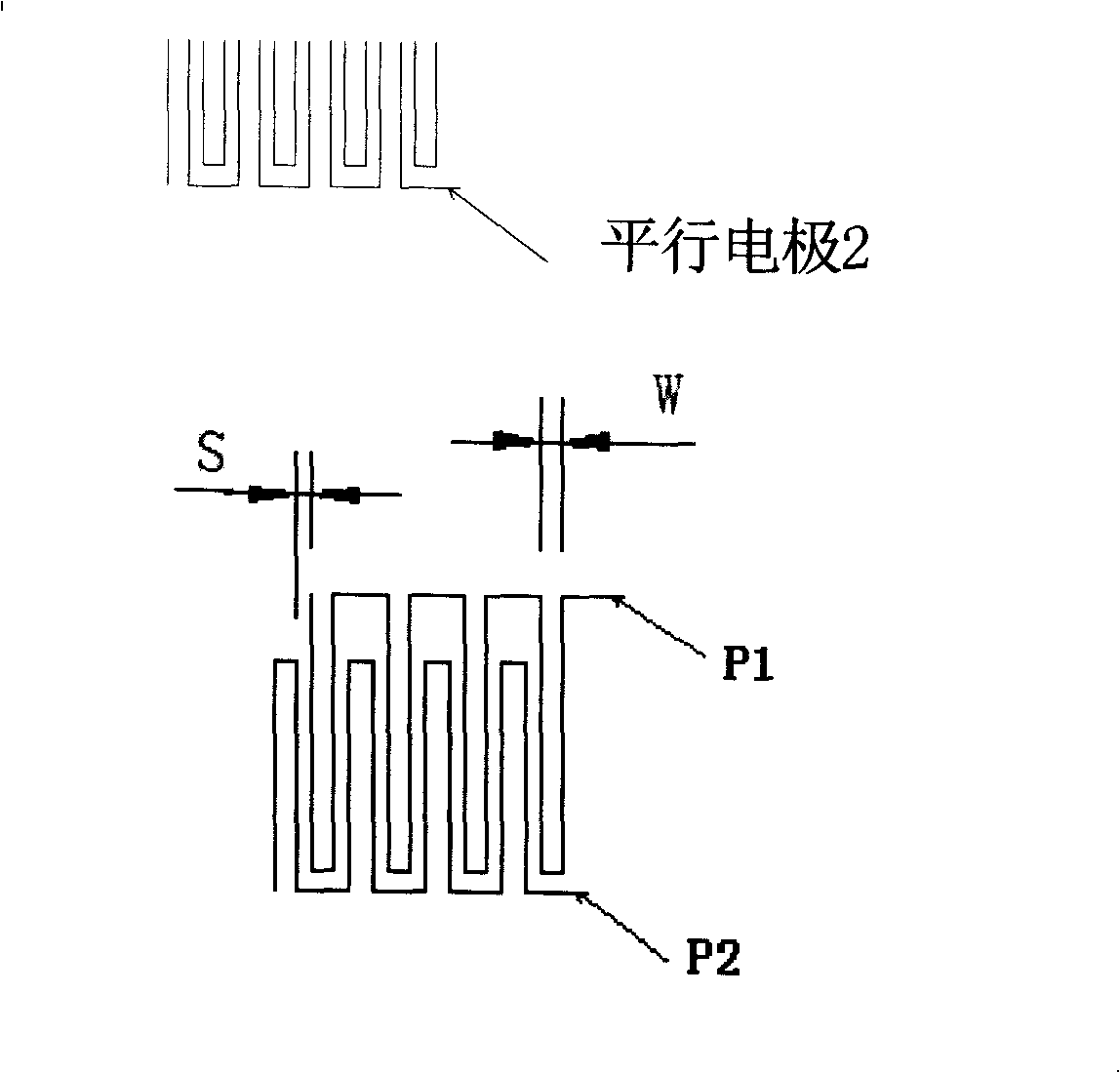
[0023] The ITO test board ITO conductive layer is divided into a first part A and a second part B, each part includes three areas, wherein the first part A includes the first area 1, the third area 3 and the fifth area 5; the second part Part B includes the second area 2, the fourth area 4 and the sixth area 6; the areas of the first and second parts A and B are symmetrically distributed, the difference is that the first part A is coated with an insulating layer, and the second area B is not. Apply insulation. Each region is distributed with two sets of parallel electrodes composed of ITO traces with the same line width, each region is connected in series, and the electrodes are not connected and the di...
Embodiment 2
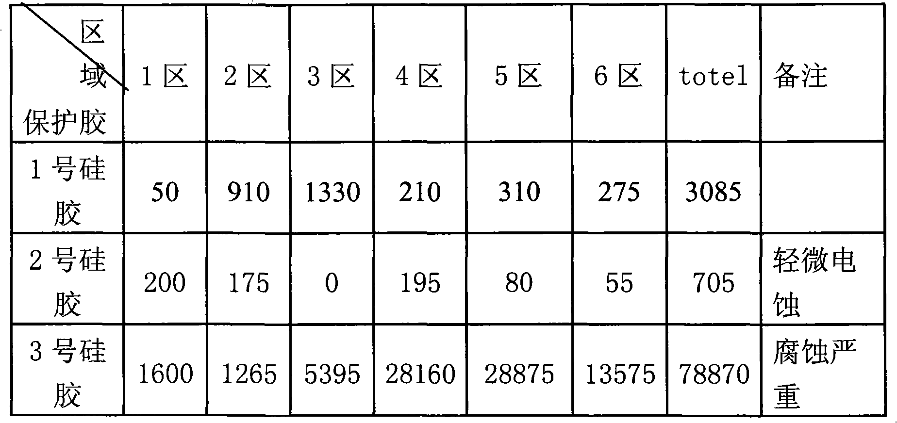
[0026] In this example, the performance of the new ITO protective glue material was evaluated using the ITO test board described in Example 1. After the three groups of test boards are ultrasonically cleaned, they are respectively coated with an insulating protective layer. The adhesive material of the insulating protective layer is the current general material No. 1 silica gel and the new material No. 2 and No. 3 silica gel. Experiments were carried out under 95% high temperature and high humidity conditions. After 48 hours, the corrosion numerical statistics were carried out according to the quantitative method provided in the above example, and the following data table 1 was obtained:
[0027] Data Sheet 1
[0028]
[0029] According to the data table 1, it can be clearly seen that the anti-corrosion effect of the new material No. 2 silica gel is significantly improved compared with the currently used material No. 1 silica gel. After such an evaluation, the pros and co...
Embodiment 3
[0032]This example is based on the ITO test board described in Example 1, and the quantitative method provided above is used to evaluate the reliability test and the anti-corrosion ability of existing projects.
PUM
 Abstract
Description
Claims
Application Information
 - R&D
- Intellectual Property
- Life Sciences
- Materials
- Tech Scout
- Unparalleled Data Quality
- Higher Quality Content
- 60% Fewer Hallucinations
Browse by: Latest US Patents, China's latest patents, Technical Efficacy Thesaurus, Application Domain, Technology Topic, Popular Technical Reports.
© 2025 PatSnap. All rights reserved.Legal|Privacy policy|Modern Slavery Act Transparency Statement|Sitemap|About US| Contact US: help@patsnap.com


