
Lightning protection device of windmill blade

A protection device and blade technology, applied in wind power generation, cable installation, wind turbine components, etc., can solve problems such as no disclosure, and achieve the effects of simplifying the structure, avoiding the increase of air pressure, and preventing the blade from breaking.

Active Publication Date: 2009-01-07
MITSUBISHI HEAVY IND LTD
View PDF2 Cites 13 Cited by
  • Summary
  • Abstract
  • Description
  • Claims
  • Application Information

AI Technical Summary

Problems solved by technology

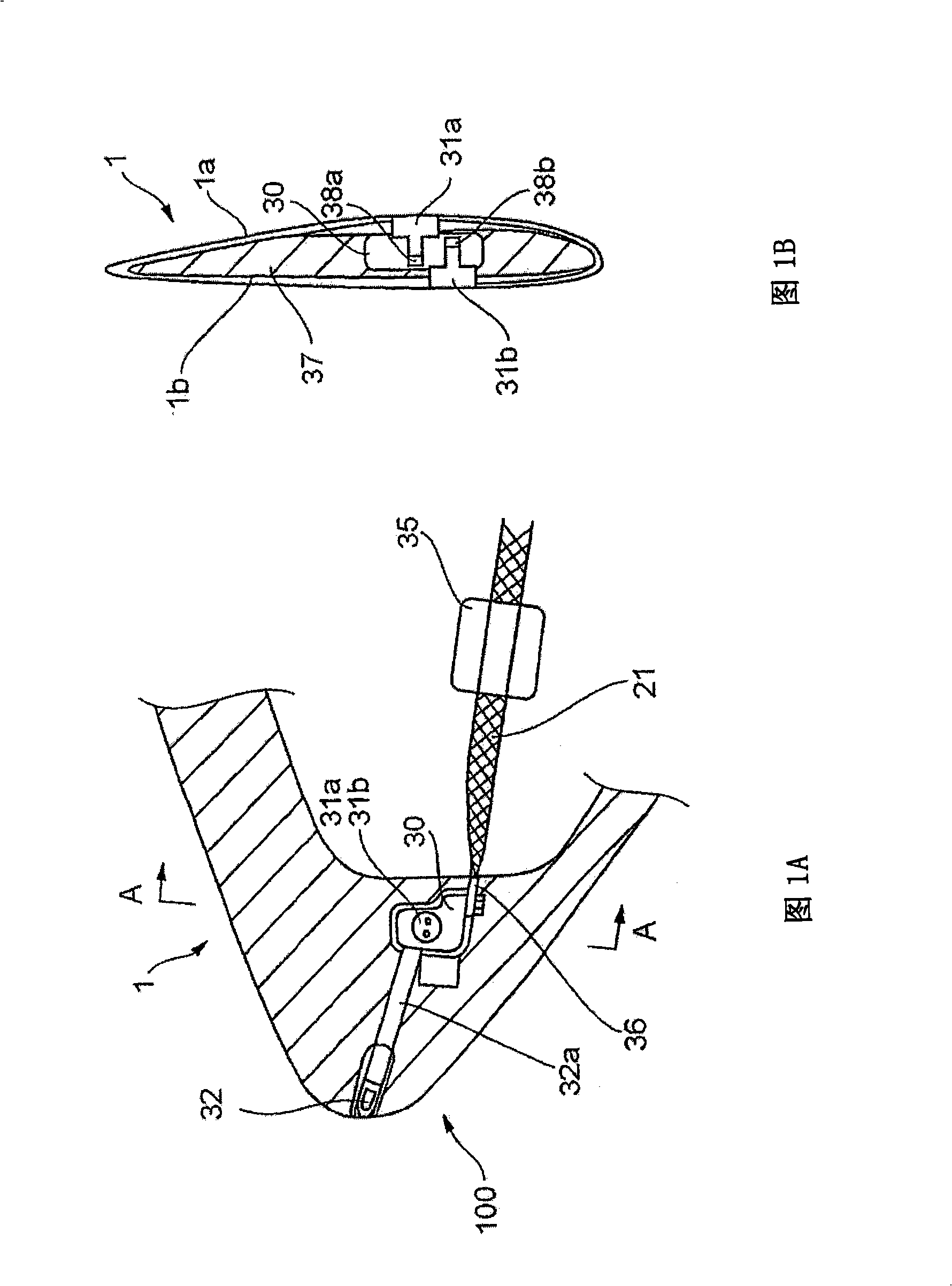
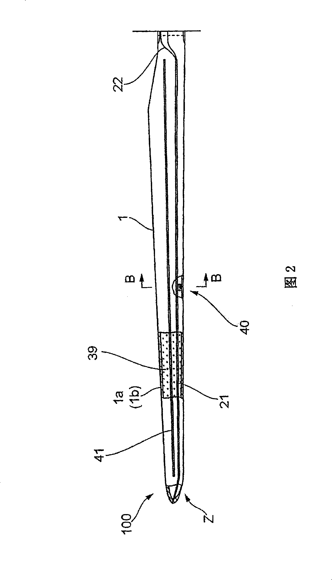
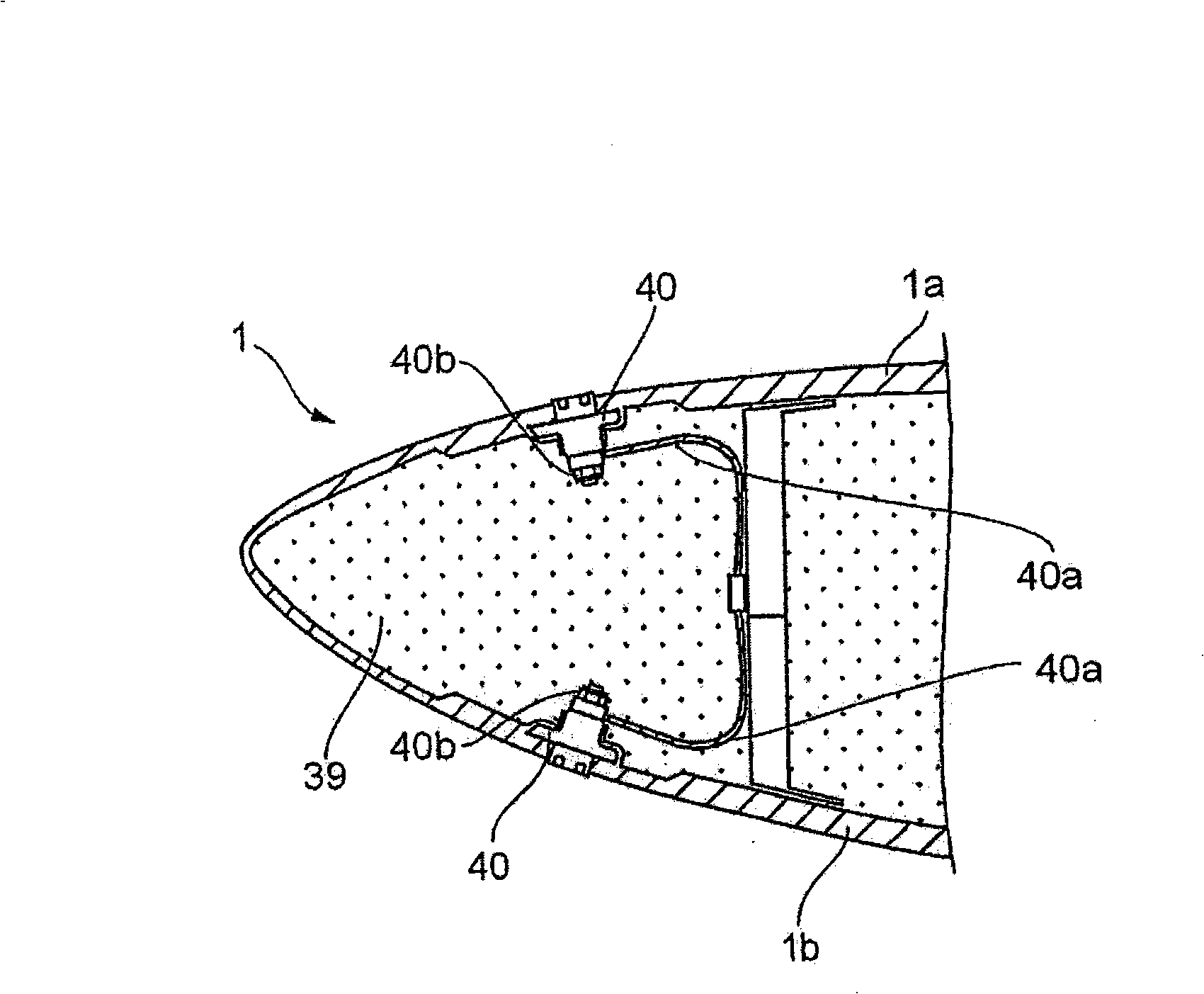
[0005] However, although the technique disclosed in Patent Document 1 relates to a structure in which lightning current from a lightning receiver (the lightning receiver runs from the tip of the blade along the blade The length direction of the blade is arranged at several positions), and although the technology disclosed in Patent Document 2 involves lightning receivers exposed on the ventral shell of the blade and the back shell of the blade to allow lightning to strike the lightning receiver At the same time, the receiver is fixed to the rear surface of the ventral shell and the structure of the dorsal shell respectively by screws, but neither of the two patent documents discloses a method for assembling the receiver to a blade with a smaller airfoil profile. Effective measures at the tip portion, countermeasures against pressure increase caused in the inner side of the blade when lightning strikes the blade, etc.

Method used


Image

  • Lightning protection device of windmill blade
  • Lightning protection device of windmill blade
  • Lightning protection device of windmill blade

Examples


Embodiment Construction

[0027] The embodiments of the present invention shown in the drawings will be described in detail below. It should be noted that the size, material, shape, and relative arrangement of the component parts described in this embodiment cannot be considered as limiting the scope of the present invention, that is, these are just some examples.

[0028] Reference Figure 4 , Figure 4 It is a schematic side view of a windmill equipped with a lightning protection device according to the present invention, showing the presence of a rotor head 2, a plurality of blades connected to the outer periphery of the rotor head 2, a main shaft 3 constituting the output shaft of the rotor head 2, and a main bearing 4. Generator 8. Speed-increasing gear 5 for increasing the speed of the rotor head 2 to the rated speed of the generator 8, a coupler for connecting the speed-increasing gear 5 with the generator 8 6, Engine compartment 7, An engine compartment chassis panel 7a supporting the engine compartm...


PUM


Abstract

The present invention proposes a lightning protection device of a windmill blade, comprising a tip receptor assembly having receptors which are mounted, in particular to, the tip end part of the blade where the blade profile becomes smaller, and having a simple structure so as to be readily assembled, and an intermediate receptor assembly having a receptor which is set at the outer surface of the blade so as to exhibit an effective countermeasure against increasing of the air pressure in the blade upon a lightning striking upon the blade, a lightening current being discharged to the ground from the receptors through connection equipment such as lead wires laid through the inside of the blade the windmill body and bypass brushes, characterized in that a base plate made of an electrically conductive material and connected thereto with the lead wires is embedded in the blade, and the receptors are secured and supported to the base plate, being exposed at the outer surface of the blade. Further, the present invention also proposes a method of assembling the lightning protection device.

Description

Technical field [0001] The present invention relates to a lightning protection device for windmill blades and a method for assembling the lightning protection device. The lightning protection device includes: a lightning receiver connected to the outer surface of the blade, and lightning current is passed from the receiver through, for example, laying It is released to the ground through connecting devices such as conductors inside the wind turbine blades; and the wind turbine body part or bypass brush. Background technique [0002] As a measure to prevent the turbine blades of the windmill or the entire windmill device from being struck by lightning, for example, Patent Literature 1 (PCT-WO2004 / 111686A1) or Patent Literature 2 (PCT-WO2005 / 026538A1) proposes a lightning protection device, It includes: a lightning receiver connected to the outer surface of the blade, and the lightning current caused by the lightning hitting the receiver is guided from the outer surface to the grou...

Claims


Application Information

Patent Timeline
IPC IPC(8): F03D11/00H05F3/04
CPCY02E10/722H02G13/00F03D11/0033F03D80/30H02G13/40H02G13/80Y02E10/72Y10T29/49337F03D1/0658
Inventor 有永真司柴田昌明中村直靖松下崇俊堤和久黑岩隆夫平野敏行刈迂界
Owner MITSUBISHI HEAVY IND LTD
Learn More