
Flue gas denitrating whirling current mixer and whirling current mixing method

A mixer and eddy current technology, applied in chemical instruments and methods, separation methods, dispersed particle separation, etc., can solve the problems of large system pressure loss, large resistance, large flue area, etc., and achieve strong flue gas adaptability and debugging. Short time, good mixing effect

Inactive Publication Date: 2009-01-14
BEIJING GUODIAN LONGYUAN ENVIRONMENTAL ENG
View PDF0 Cites 20 Cited by
  • Summary
  • Abstract
  • Description
  • Claims
  • Application Information

AI Technical Summary

Problems solved by technology

[0008] However, after long-term operation, it was found that because the grid mixer occupies a very large area of ​​the flue, the resistance is relatively large, and the pressure loss of the system is relatively large.
At the same time, nozzle clogging occurs from time to time, resulting in uneven mixing of ammonia, which seriously affects the denitrification efficiency, and the system adjustment is very complicated, and failures often occur

Method used


Image

  • Flue gas denitrating whirling current mixer and whirling current mixing method
  • Flue gas denitrating whirling current mixer and whirling current mixing method
  • Flue gas denitrating whirling current mixer and whirling current mixing method

Examples


Embodiment 1

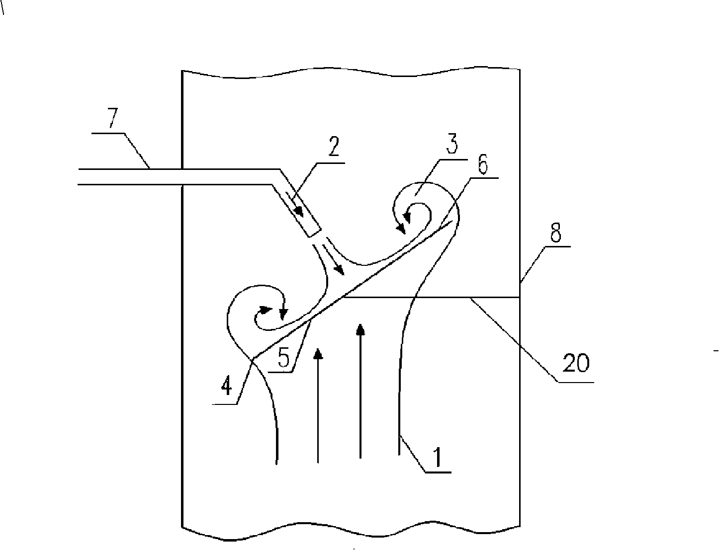
[0031] Embodiment one sees figure 1 As shown, this flue gas denitrification vortex mixer includes a mixing element placed in the flue 8 and a reducing agent nozzle 7 inserted into the flue. It is fixedly connected with the inner wall of the flue, the backflow surface 6 of the mixing element is a plane, the angle between the backflow surface and the flow direction of the flue gas is 10°-90°, and it is facing the nozzle of the reducing agent nozzle 7, but not in contact with The nozzles of the reducing agent nozzles are in contact with each other, and the flow surface 5 of the mixing element faces the flow direction of the fluid.

[0032] The plane of the sheet-like mixing element 4 may be circular, elliptical, rectangular, trapezoidal or other polygonal shapes adapted to the cross-sectional shape of the flue. The mixing element is made of carbon steel or other materials resistant to high temperatures of 450°C. The diameter of the mixing element does not exceed 80% of the cros...

Embodiment 2

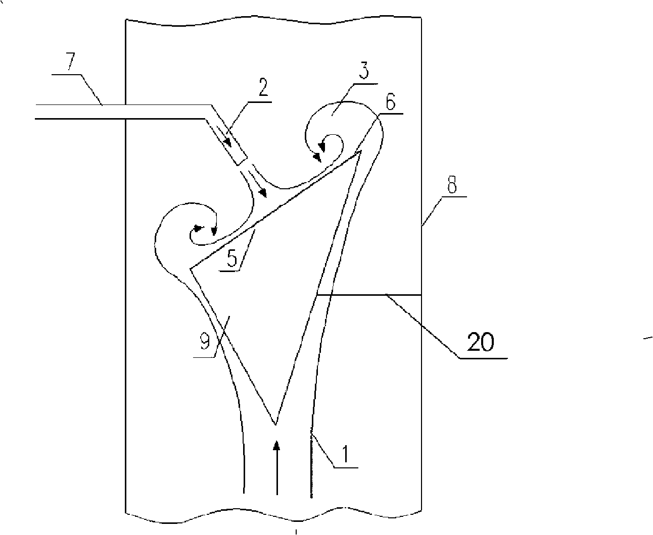
[0034] Embodiment two see figure 2 As shown, the difference from Example 1 is that the flue gas denitrification vortex mixer uses a conical mixing element 9, and the above-mentioned conical mixing element 9 is a right conical, oblique conical, elliptical conical, equilateral pyramid or unequal pyramid The bottom surface of the cone is the reverse flow surface, and the tip of the cone faces the flow direction of the flue gas 1.

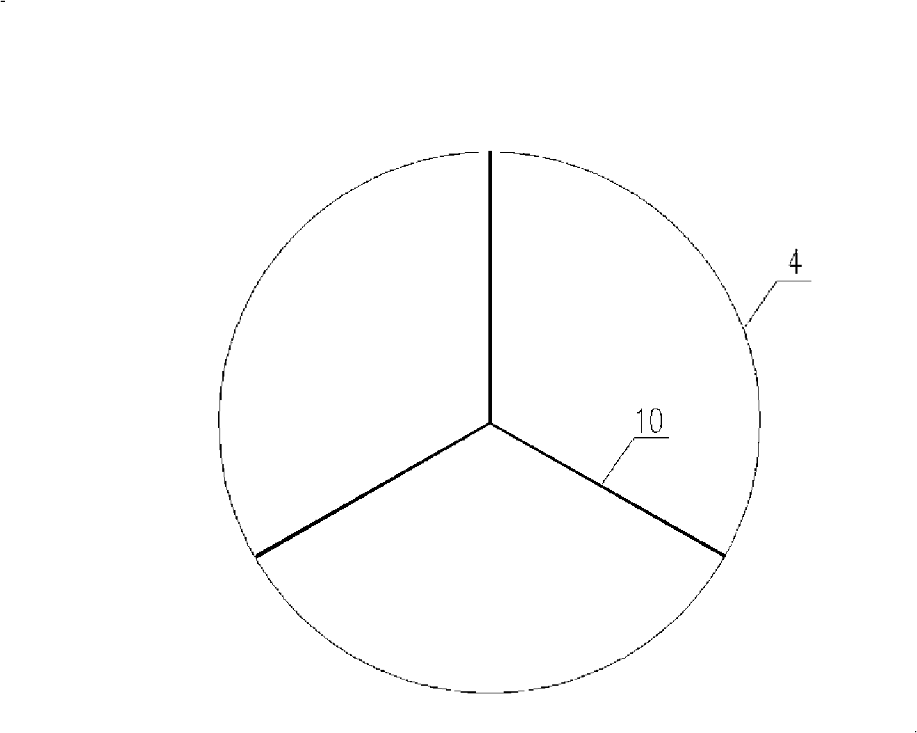
[0035] see image 3 , the backflow surface of the above-mentioned mixing element 4 may be fixed with a radial partition plate 10 that divides the surface 3-n into equal parts. The divider acts as a flow guide, which can make the air distribution more even.

[0036] For regularly shaped mixing elements, the reducing agent, ammonia, can be sent to the center of the backflow surface, which is at the center of gravity of the plane. For mixing elements with irregular shapes, such as unequal triangular pyramids, trapezoids or similar polygonal mixing ele...


PUM


Abstract

The invention relates to an eddy flow mixer for smoke gas denitration and an eddy-mixing method; the mixer comprises a mixing component arranged in a gas flue and a reducing agent nozzle inserted in the gas flue; the lee face of the mixing component is a flat surface and directly faces the spout of the reducing agent nozzle and does not contact with the spout of reducing agent nozzle; the stoss side of the mixing component faces toward the flow direction of a fluid. A denitration system adopting the invention utilizes the eddy flow formed by the smoke gas to evenly mix ammonia of the reducing agent, which makes the deviation of mixing uniformity of NH<3> / NO on various points on the cross-section of the inlet of a first catalyst layer be within plus or minus 5 percent so as to totally achieve perfect mixing of NH<3> / NOx. The eddy flow mixer for smoke gas denitration and the eddy-mixing method are especially suitable for the smoke gas denitration technology by a selective catalytic reduction in a thermal power plant, which introduces the ammonia of the reducing agent into the smoke gas containing nitrogen oxide and mixes evenly.

Description

technical field [0001] The invention relates to a device for uniformly mixing two or more gases in a flue gas denitrification process, and a vortex mixing method using the device. Background technique [0002] The main source of nitrogen oxides in the atmosphere is fuel, of which nearly 70% comes from the direct combustion of coal. my country is a country where coal is the main energy source, and the coal consumption of thermal power plants accounts for more than half of my country's total coal consumption. According to statistics, the total amount of NOx emissions in my country in 2000 was about 18.8 million tons, of which the nitrogen oxide emissions from thermal power plants were 4.96 million tons. According to the current emission level, it is estimated that by 2020, the nitrogen oxides emitted by thermal power plants in my country will reach more than 10 million tons. The increase of NOx concentration will increase the oxidation of the atmosphere, leading to a series ...

Claims


Application Information

Patent Timeline
Patent Type & Authority Applications(China)
IPC IPC(8): B01D53/79B01D53/56
Inventor 赵禹路光杰刘汉强吴敌沈滨
Owner BEIJING GUODIAN LONGYUAN ENVIRONMENTAL ENG
Learn More