Wave-guide coupling microstrip/strip line filter

A filter and stripline technology, applied in the field of filters, can solve problems such as unfavorable scale production, characteristic deterioration, filter offset, etc., and achieve the effects of avoiding surface mount technology, improving out-of-band suppression, and convenient assembly and disassembly

Inactive Publication Date: 2009-01-28
上海杰盛无线通讯设备有限公司
View PDF0 Cites 13 Cited by
  • Summary
  • Abstract
  • Description
  • Claims
  • Application Information

AI Technical Summary

Problems solved by technology

However, as the frequency increases, the circuit size decreases relative to the wavelength, and the same processing error will cause a large change in the amplitude-frequency characteristics of the filter, resulting in filter passband shift, out-of-band rejection, and in-band fluctuations The characteristics deteriorate, resulting in the failure of the circuit performance to meet the expected design index requirements
On the other hand, only after all components of the microwave hybrid circuit are mounted can it be tested to determine whether the filter meets the index requirements. Once it does not meet the requirements, it means that the expensive microwave integrated circuits that have been mounted are scrapped, causing major economic losses.
In order to solve this problem, someone has proposed a surface mount microstrip filter. Although the filter is separated from the circuit module for replacement of the filter, the application of the surface mount process to a filter with a large area is still not conducive to mass production. And the filter pins and solder joints will introduce parasitic effects that are difficult to estimate, affecting the index and consistency of the filter

Method used


Image

  • Wave-guide coupling microstrip/strip line filter
  • Wave-guide coupling microstrip/strip line filter
  • Wave-guide coupling microstrip/strip line filter

Examples


Embodiment Construction

[0033] Please refer to the accompanying drawings for a further description of the present invention.

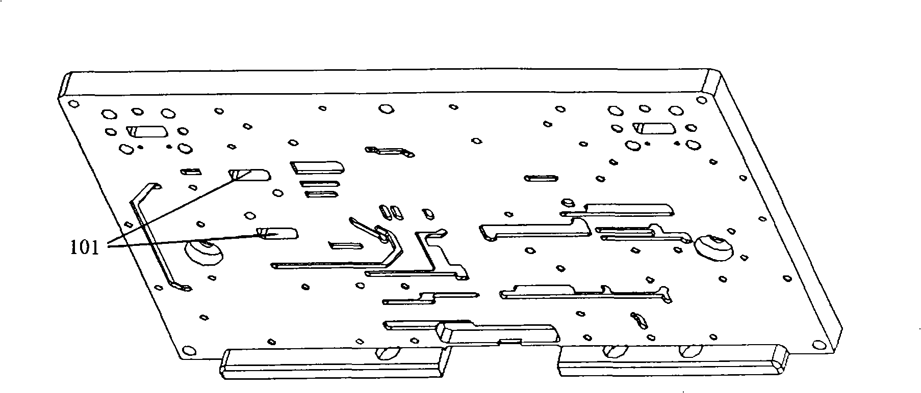
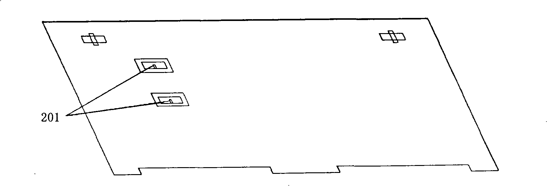
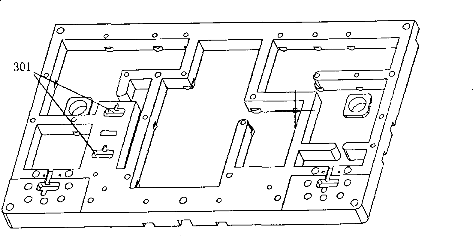
[0034] The present invention provides a waveguide coupling microstrip / stripline filter, which includes a shielding box cover plate 3, a microwave hybrid circuit board 2, a shielding box bottom plate 1, a filter plate 4 and a filter cover plate 5 in a microwave transceiver module , the filter board 4 is separated from the microwave hybrid circuit board 2, and after separation, the two adopt waveguide coupling, that is, two rectangular waveguide ports 101 are opened on the bottom plate 1 of the shielding box, corresponding to the filter board 4 and the microwave hybrid circuit board 2 position, setting the microstrip or stripline-to-waveguide transition.

[0035] Such as figure 1 and figure 2 As shown, the two rectangular waveguide openings 101 on the bottom plate 1 of the shielding box correspond to the microstrip or stripline-waveguide conversion positions on the microwave...


PUM


Abstract

The invention provides a waveguide coupling micro-strip/band-shaped line filter, comprising a cover board for a shielding box in a microwave transceiving module, a microwave mixing circuit board, a base plate for the shielding box, a plate for a filter and a cover board for the filter, wherein the plate for the filter is separated from the microwave mixing circuit board and is coupled with the microwave mixing circuit board in a waveguide way, that is, the cover board for the shielding box is provided with two rectangular waveguide openings, the plate for the filter is provided with a micro-strip or strip-shaped line-waveguide converter corresponding to the microwave mixing circuit board; and a signal on the microwave mixing circuit board is coupled to the plate for the filter through the strip-shaped line-waveguide converter, and microwave mixing circuit board is filtered, strip-shaped line-waveguide converted and coupled so as to realize the micro-strip filter function. The waveguide coupling micro-strip/band-shaped line filter has the advantages of improving the maintainability, producibility and debugging performance of the product, improving the spurious suppression, solving the problems of microwave transmission line and the power cord intersection in the routing process of the double-surface circuit board, and improving the performance of the product.

Description

technical field [0001] The invention relates to a filter in microwave communication, in particular to a waveguide coupling microstrip / stripline filter in a microwave hybrid circuit. Background technique [0002] Hybrid microwave circuits are widely used in communication, remote sensing, national defense and other fields, and filters are important components of hybrid microwave circuits. In the microwave band, the filter in the hybrid microwave circuit is usually in the form of microstrip or stripline, which has the characteristics of compact structure, and the theory of calculating this type of filter is quite mature, the accuracy of simulation calculation is high, and it is easy to design and integrate. However, as the frequency increases, the circuit size decreases relative to the wavelength, and the same processing error will cause a large change in the amplitude-frequency characteristics of the filter, resulting in filter passband shift, out-of-band rejection, and in-ban...

Claims


Application Information

Patent Timeline
Patent Type & Authority Applications(China)
IPC IPC(8): H01P1/203H01P5/08
Inventor 陈松麟张宇黄光煌
Owner 上海杰盛无线通讯设备有限公司
Why Eureka
Try Eureka