

Combined electrolytic cathode plate
An electrolysis cathode plate and combined technology, applied in the direction of electrodes, electrolysis process, electrolysis components, etc., can solve the problems of high labor intensity for workers, take up a lot of time, increase the area of the electrolysis cathode plate, and reduce the installation The effect of reducing the working time of the tank, improving production and labor efficiency, and increasing the effective time of electrolysis
- Summary
- Abstract
- Description
- Claims
- Application Information
AI Technical Summary
Problems solved by technology
Method used
Image

Examples
Embodiment 1
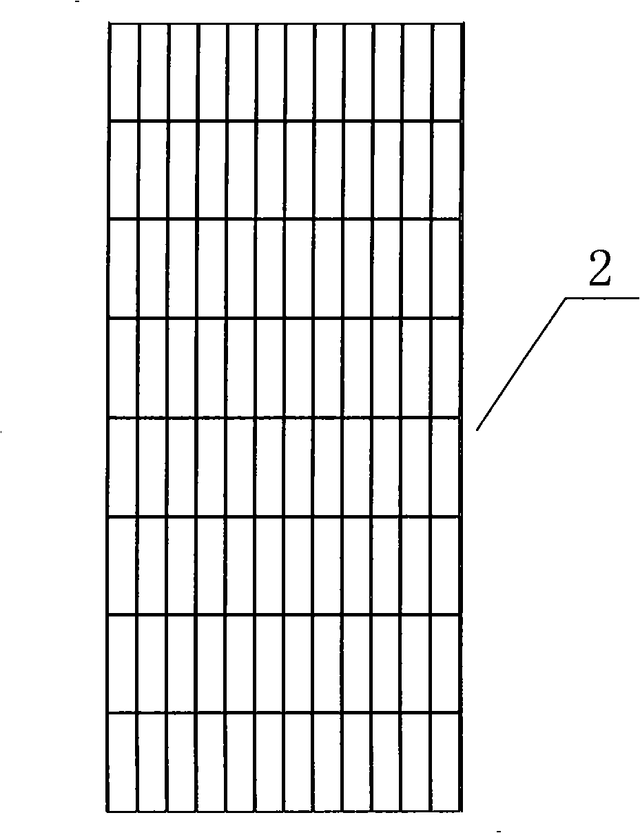
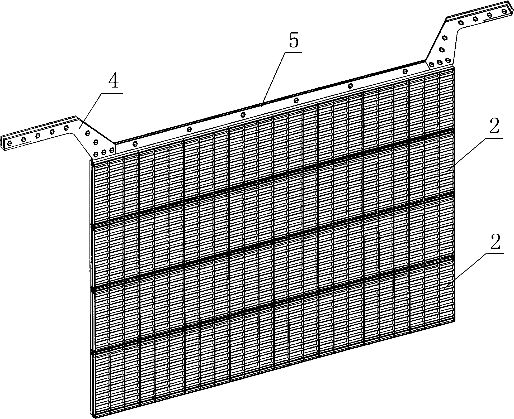
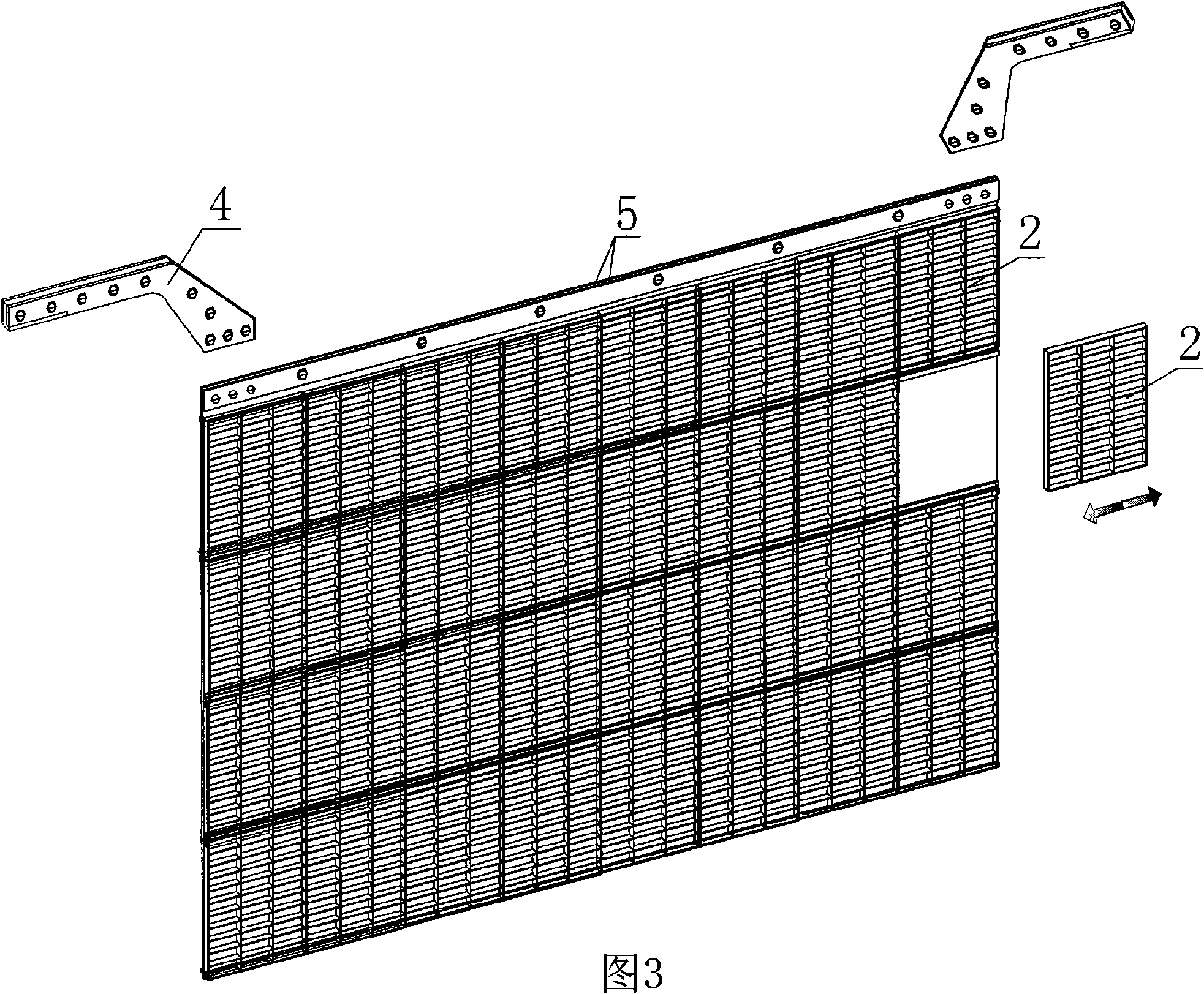
[0070] Such as Figure 2 to Figure 15 A combined electrolysis cathode plate shown is one of the embodiments of the present invention, and it includes an electrolysis mother board 1, a plurality of electrolysis unit boards 2 and their connecting mechanisms and conductive connectors. The electrolysis mother board 1 is a flat plate structure with The upper end edge 11 and the plate body 12, the upper end edge 11 of the electrolytic mother board 1 is connected with the conductive connector, and is used for the circuit conduction of the electrolytic cathode plate. On the body 12, the area of the electrolytic mother plate is 32-1=31 times larger than the electrolytic unit plate.
[0071] Both sides of the body 12 of the electrolytic mother board 1 are assembled with electrolytic unit boards 2, and each side is provided with four pairs of guide rail connection mechanisms 13 parallel to each other along the transverse direction (X direction). 1. The four secondary guide rails 13 on...
Embodiment 2
[0076] Figure 16 to Figure 19 A combined electrolytic cathode plate shown is the second embodiment of the present invention, which consists of electrolytic mother board 1, 32 electrolytic cell boards 2 and their connecting mechanisms and conductive connectors. The difference from the first embodiment is the connection The mechanism adopts a hanging connection structure, which is composed of 8 pairs of hanging rails 101 arranged longitudinally (Y direction) on the front and back of the electrolytic motherboard, and each pair of hanging rails 101 is respectively provided with 4 pairs of hooks 102 from top to bottom. The electrolytic unit board 2 is also provided with a hanging block 201 adapted to each pair of hooks 102 on the electrolytic mother board 1, and the hanging block 201 on the electrolytic unit board 2 is hung on the hook 102 on the electrolytic mother board 1. To realize its installation on the electrolytic mother board 1; when dismounting, it is only necessary to r...
Embodiment 3
[0078] Figure 25 to Figure 26 The shown combined electrolytic cathode plate is the third embodiment of the present invention, and the difference between it and another variation (see FIGS. 20 to 24) in the first embodiment is the plate body 12 of the electrolytic mother plate 1 It is a stencil structure, and each of its two sides is provided with 8 pairs of guide rail connection mechanisms 13 parallel to each other along the longitudinal direction (Y direction), and a supporting electrolysis is provided at the bottom end of each of the two sides of the body 12 of the electrolytic motherboard 1. The support 12a of the unit board 2, each pair of guide rails is composed of an "L" shaped left guide rail 13a and a right guide rail 13b, and each guide rail forms a "U" shaped track with the electrolytic motherboard 12, and each pair of guide rails 4 The openings are opposite, that is, the opening directions of each left guide rail 13a are all to the right, and the opening directions...
PUM
 Abstract
Description
Claims
Application Information