Check patentability & draft patents in minutes with Patsnap Eureka AI!

Combined double preheating device

A preheating device, combined technology, applied in blast furnace parts, furnaces, heating furnaces, etc., can solve the problems of high price and tension, and achieve the best effect of increasing temperature, increasing physical heat, and saving energy.

Inactive Publication Date: 2009-02-11
袁长胜
View PDF0 Cites 15 Cited by
  • Summary
  • Abstract
  • Description
  • Claims
  • Application Information

AI Technical Summary

Problems solved by technology

Steel plant coke oven gas or natural gas are very tight and expensive

Method used


Image

  • Combined double preheating device
  • Combined double preheating device
  • Combined double preheating device

Examples


Embodiment 1

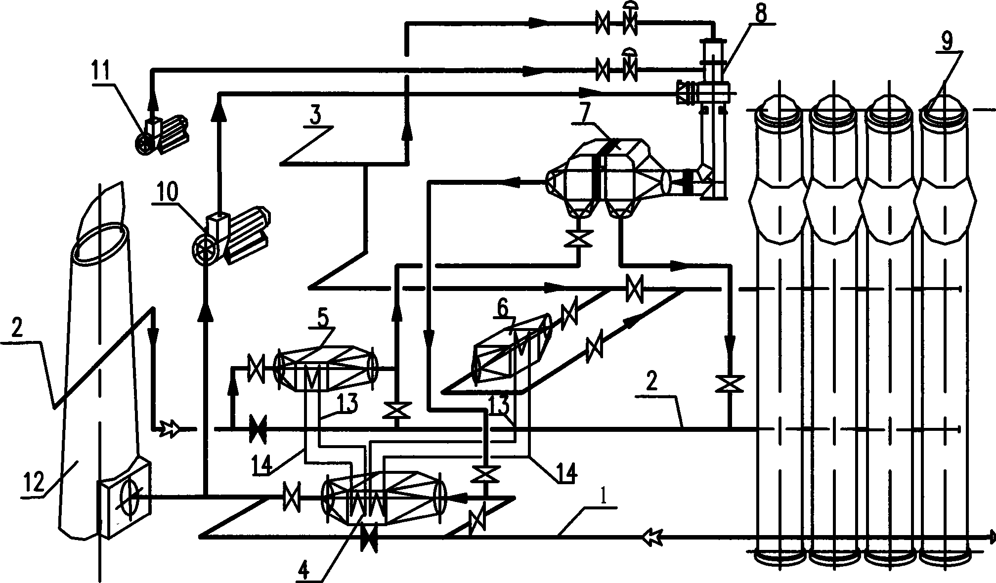
[0013] Embodiment 1: as figure 1 As shown, the first-stage preheater of the combined preheater is a separate heat pipe heat exchanger; the second stage is a shell-and-tube heat exchanger and is equipped with a new flue gas generator. The separated heat pipe heat exchanger is composed of three heat exchangers 4, 5, 6 for flue gas 1, air 2 and coal gas 3 and connecting pipes (rising pipe 13 and descending pipe 14). The first stage of preheating is to use the sensible heat of flue gas from the hot blast stove to heat the medium in the heat pipe in the flue gas heat pipe heat exchanger 4, so that it is vaporized into steam and enters the air heat pipe heat exchanger 5 and the gas heat pipe respectively along the riser pipe 13. Heat exchanger 6 heats the air to about 180°C and the gas to about 200°C. After the medium in the heat pipe gives heat to the air and gas, it is cooled to water and then flows back to the flue gas heat pipe heat exchanger 4 along the downcomer 14 to be heat...

Embodiment 2

[0019] Example 2: As shown in Figure 2, the primary preheating device of the combined preheating device is an integral heat pipe heat exchanger; the second stage is a shell and tube heat exchanger, and is equipped with a new type of flue gas generator . The integral heat pipe heat exchanger is composed of a number of single heat pipes, a box and a partition, etc. (the difference between embodiment 2 and embodiment 1 lies in the first-stage preheating device). The heating end of a single heat pipe is placed in the flue gas heat exchange side box of the integral heat pipe heat exchanger; the cooling end is placed in the air heat exchange side box or the gas heat exchange side box. With the heat transfer function of each heat pipe, part of the heat of the flue gas is transferred to the air and gas. Make the air temperature reach about 180°C; make the gas temperature reach about 200°C.

[0020] The preheating process flow of the second stage is the same as that of Embodiment 1, ...


PUM


Abstract

The present invention provides a united preheating equipment which consists of a first class and a second class preheating devices; the flue gas enters an air heat pipe exchanger and a coal gas heat pipe exchanger respectively after sent into a heating pipe of a flue gas heat pipe exchanger and vaporized into steam, and the air enters a second level of the tube high temperature air exchanger after preheated by first level preheating, and the high temperature flue gas which is sent by a flue gas generator is heated by second level, then the heated air is sent into a combustion chamber of a hot blast stove; the coal gas is sent into the combustion chamber of the hot blast stove directly after preheating. The invention not only fully utilizes the flue gas residual heat resources to achieve the optimization of the energy-saving effect, but also adopts the flue gas generator, the oxidizing air preheated by the first level is further heated to 500 DEG C, so as to greatly increase the physical hot value of the gas which is sent into the combustion chamber of the hot blast stove, thereby greatly raising the temperature of the flame in the combustion chamber of the hot blast stove and the temperature of the checker brick in a regenerator, so as to make sure that the temperature of the air supply reaches over 1200-1250 DEG C.

Description

technical field [0001] The invention relates to an auxiliary equipment of a blast furnace hot blast stove, in particular to a combustible air and blast furnace gas combined double preheating device with a flue gas generator. Background technique [0002] With the advancement of blast furnace smelting technology, such as gradually increasing the amount of coal injection, the blast furnace coke ratio and the calorific value of blast furnace gas will decrease accordingly. The calorific value of blast furnace gas is now generally 3000KJ / Nm 3 about. In the case of fully burning blast furnace gas, the air supply temperature can only reach about 1050-1100 °C even if the waste heat recovery device is adopted. It can't reach the relatively advanced high wind temperature level of 1200-1250 ℃. To achieve this advanced level of high blast temperature, the flame temperature in the combustion chamber of the hot blast stove must be increased. For this reason, either coke oven gas or na...

Claims


Application Information

Patent Timeline
IPC IPC(8): C21B9/00
Inventor 袁长胜
Owner 袁长胜
Features
  • R&D
  • Intellectual Property
  • Life Sciences
  • Materials
  • Tech Scout
  • Unparalleled Data Quality
  • Higher Quality Content
  • 60% Fewer Hallucinations
Learn More