
Exposure system of photo-etching machine and control method thereof

A technology of exposure system and lithography machine, which is applied to microlithography exposure equipment, photolithography process exposure devices, etc., can solve the problems of long exposure time and low working efficiency of lithography machine, and achieve the effect of improving work efficiency

Active Publication Date: 2009-02-11
深圳清溢光电股份有限公司
View PDF0 Cites 15 Cited by
  • Summary
  • Abstract
  • Description
  • Claims
  • Application Information

AI Technical Summary

Problems solved by technology

[0005] The purpose of the embodiments of the present invention is to provide a lithography machine exposure system, aiming to solve the problem of low working efficiency of the lithography machine due to the long exposure time of the blank light-transmitting area around the pattern of the mask plate in the existing lithography machine exposure system The problem

Method used


Image

  • Exposure system of photo-etching machine and control method thereof
  • Exposure system of photo-etching machine and control method thereof
  • Exposure system of photo-etching machine and control method thereof

Examples


Embodiment Construction

[0017] In order to make the object, technical solution and advantages of the present invention clearer, the present invention will be further described in detail below in conjunction with the accompanying drawings and embodiments. It should be understood that the specific embodiments described here are only used to explain the present invention, not to limit the present invention.

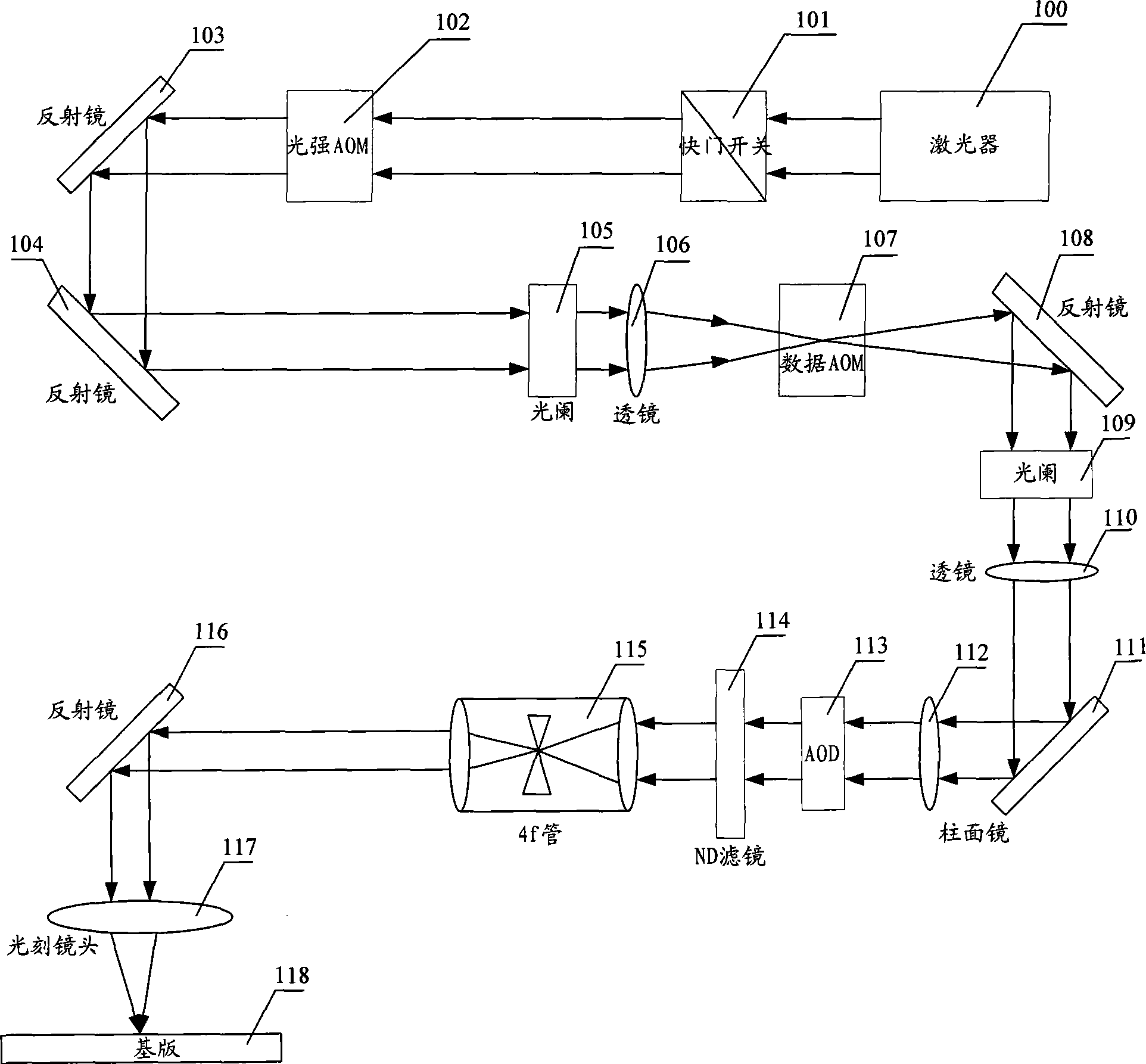
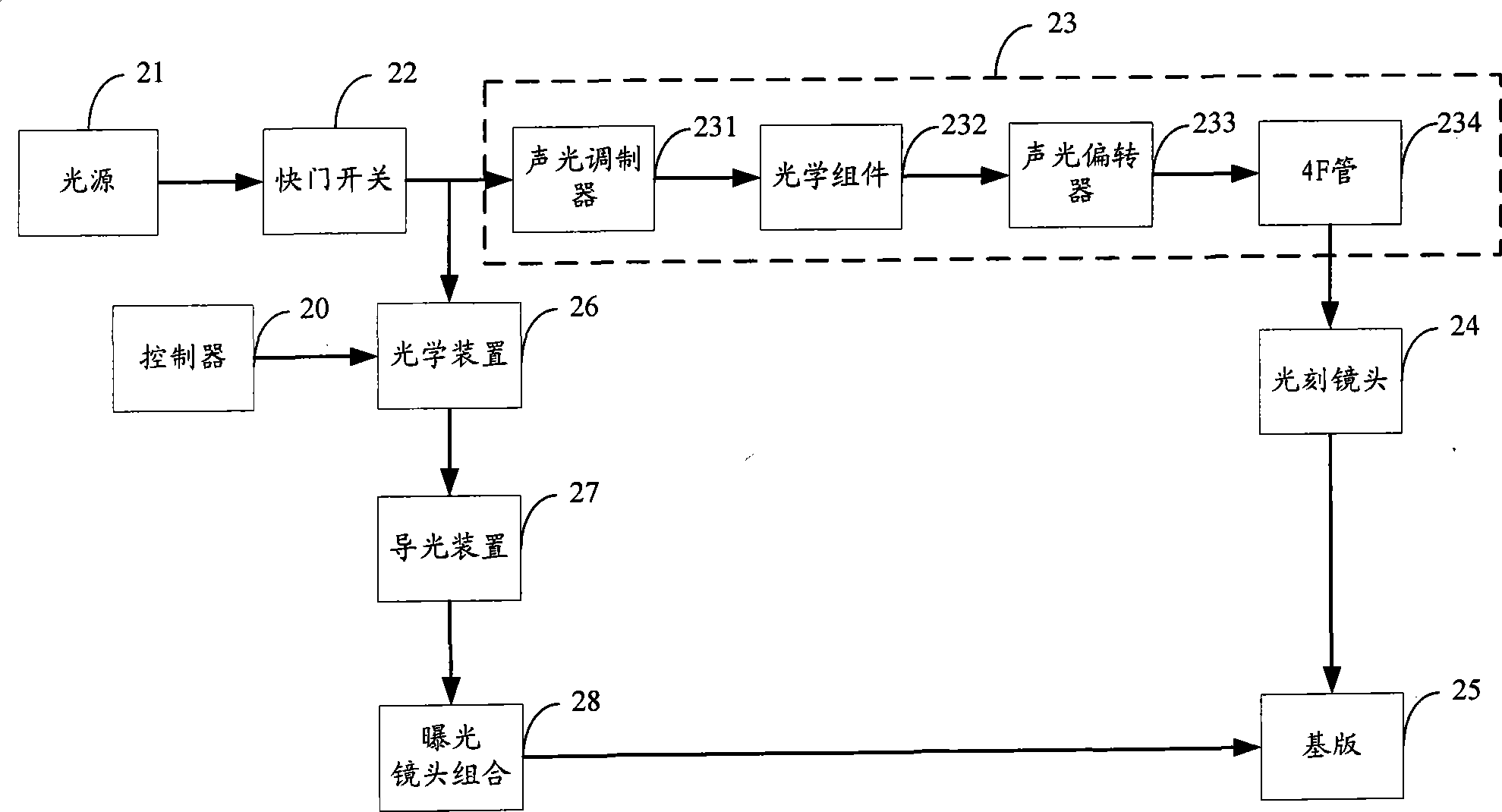
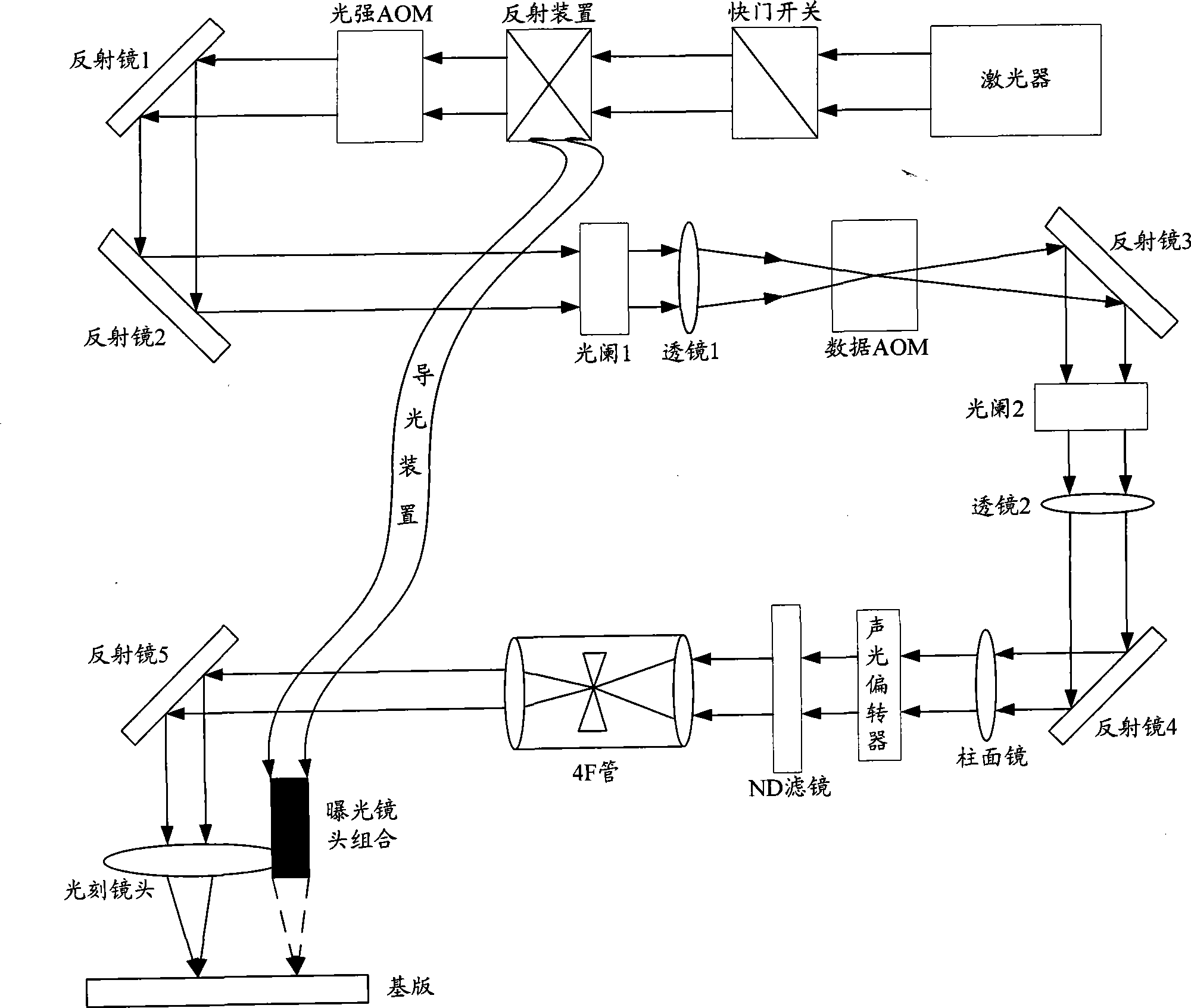
[0018] The exposure system of the lithography machine provided by the embodiment of the present invention adopts an optical device to change the propagation direction of the laser light, and forms a large spot of laser light on the base plate through a combination of lenses, so that a large blank light-transmitting area of ​​the mask plate can be quickly exposed, and the lithography process is improved. machine efficiency.

[0019] The module structure of the exposure system of the lithography machine provided by the embodiment of the present invention is as follows: figure 2 As shown, for ease o...


PUM


Abstract

The invention relates to the field of photolithography based on computer-to-plate techniques and provides a photolithographic machine exposure system and a control method thereof. The photolithographic machine exposure system comprises a light source, a light path assembly, a photolithographic lens and a substrate, which are connected in sequence. The light path assembly modulates the optical signal emitted by the light source and then outputs the optical signal. The photolithographic lens focuses the optical signal output from the light path assembly onto the substrate to form a first light spot. The photolithographic machine exposure system further comprises an optical device, a controller and an exposure lens assembly, wherein the controller controls the optical device to emit the optical signal from the light source, and the exposure lens assembly focuses the optical signal emergent from the optical device onto the substrate to form a second light spot. The diameter of the second light spot is larger than that of the first light spot. The photolithographic machine exposure system adopts the optical device to change the travel direction of the optical signal, adopts the exposure lens assembly to focus the optical signal on the substrate to form the large light spot, achieves the effect of rapid exposure of the large clear area without affecting the exposure of the fine pattern, and increase the work efficiency of the photolithographic machine.

Description

technical field [0001] The invention belongs to the field of Computer to Plate (CTP) lithography, and in particular relates to an exposure system of a lithography machine and a control method thereof. Background technique [0002] The mask making lithography machine is a device that uses laser scanning to expose computer-designed graphics on the substrate to form a latent image. It includes electrical cabinets and lithography boxes, among which the lithography machine can form a lithography system together with the graphics conversion workstation and operation terminal. The workflow of the whole system is: (1) Graphics processing: correspondingly process graphics in various formats (such as dxf, gerber, cif, gdsii, etc.) to meet the requirements of graphics conversion software (for example, for dxf graphics, you must handle solids as circles or closed polydomain lines). At the same time, operations such as adding frames and centering offsets can be completed. (2) Graphics...

Claims


Application Information

Patent Timeline
Patent Type & Authority Applications(China)
IPC IPC(8): G03F7/20
Inventor 张建国朱春辉
Owner 深圳清溢光电股份有限公司
Learn More