Wideband directional coupler of PI type dielectric wave-guide

A technology of directional coupler and dielectric waveguide, which is applied in the direction of waveguide devices, electrical components, connecting devices, etc., can solve the problems of increasing manufacturing complexity and cost, increasing coupler volume, etc., and achieves reducing device volume and manufacturing complexity The effect of reducing radiation loss and metal loss, and facilitating mass production

Inactive Publication Date: 2009-02-11
UNIV OF SCI & TECH OF CHINA
View PDF0 Cites 16 Cited by
  • Summary
  • Abstract
  • Description
  • Claims
  • Application Information

AI Technical Summary

Problems solved by technology

The axis of the waveguide in the transition section is a circular arc line with a large curvature. In order to ensure the isolation between the external input and output waveguides, the transition section is a very long arc structure, which increases the volume of the coupler; in order to avoid additional The coupling effect introduces a metal side wall perpendicular to the ground in the transition section, but this also introduces additional metal loss; and due to strict requirements on the finish and verticality of the metal side wall, it increases manufacturing complexity and cost

Method used


Image

  • Wideband directional coupler of PI type dielectric wave-guide
  • Wideband directional coupler of PI type dielectric wave-guide
  • Wideband directional coupler of PI type dielectric wave-guide

Examples


Embodiment 1

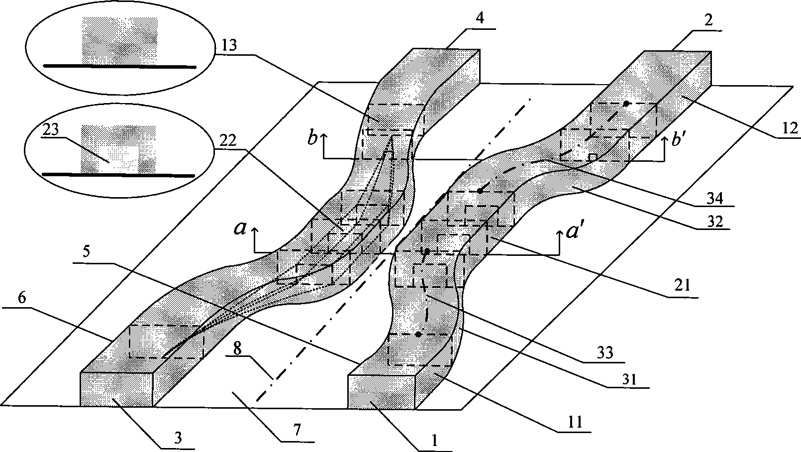
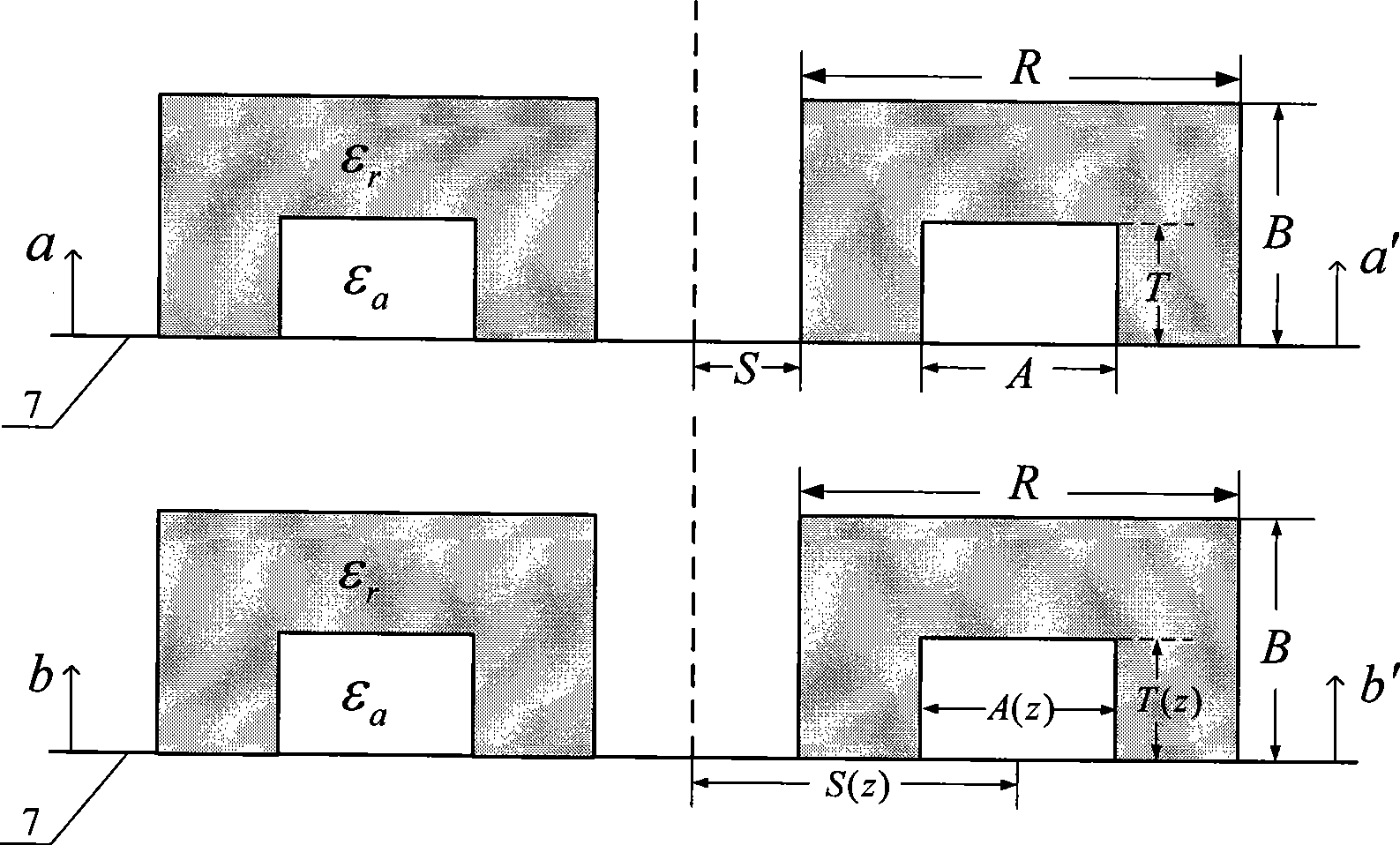
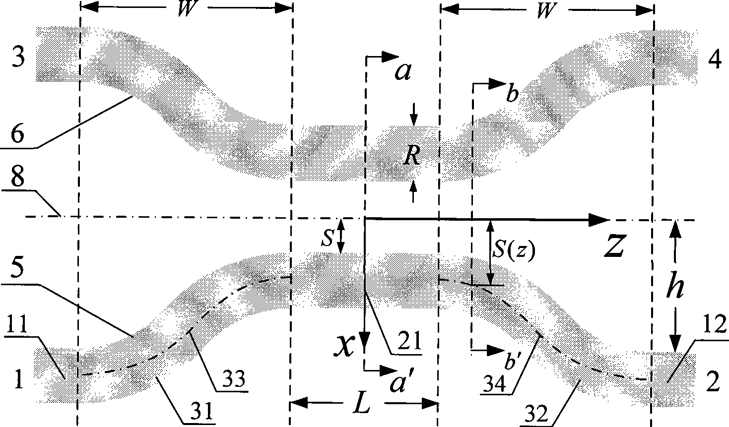
[0020] This embodiment is a Π-type dielectric waveguide 3dB broadband directional coupler, which consists of two left and right dielectric waveguide transmission lines that are placed symmetrically on both sides of the central axis 8 and that are close to but not in contact with each other and are fixed on the grounded metal plate 7. Similar to the X-shaped structure, its structure is shown in the attachment figure 1 ; The central cross-section a-a' section of the coupling region and the b-b' section view of the waveguide cross-section in the transition section are shown in figure 2 , image 3 It is a top view of the overall structure of the coupler. In this embodiment, the Π-type dielectric waveguide 3dB broadband directional coupler adopts a common dielectric constant ε r It is 2.1 polytetrafluoroethylene material, the design center operating frequency is 37GHz, and it is required to achieve a flat 3dB coupling output in the 34-40GHz frequency range, and the coupling coef...


PUM


Abstract

The invention discloses a reversed-U-type dielectric waveguide wideband directional coupler used for a millimeter wave circuit, which is composed of two medium waveguide transmission lines and an earthing metal plate, wherein two medium waveguide transmission lines close to each other are oppositely bent, arranged separately and symmetrically at two sides of an axle wire and fixed on the earthing metal plate, so as to form an X-type structure; the coupler is characterized in that the reversed-U-type medium waveguide is used for reaching of the wideband plat coupling of the coupling section and the transition section of a coupler, and the waveguide axes of the transition section adopts hyperbolic tangent line type; the fluctuation of a coupling coefficient doesn't exceed plus or minus 0.5Db inside the frequency coverage of 6GHz, and the flat coupling property can be achieved inside wider bandwidth. Compared with the traditionally directional coupler which is completely composed of a medium mirror image line, the inverted-U-type dielectric waveguide wideband directional coupler has the advantages that transition waveguide section of the hyperbolic tangent line type is used, the metal side wall of the prior coupler which is vertical to ground in the transition waveguide section is unnecessarily used, radiation loss and metal loss are reduced, the volume of the coupler is decreased and manufacture complexity and cost are reduced, and can be conveniently produced in large quantity.

Description

technical field [0001] The invention belongs to the technical field of directional couplers for millimeter wave circuits, in particular to a Π-type dielectric waveguide broadband directional coupler. Background technique [0002] In existing microwave engineering, directional couplers are mainly designed using microstrip line structures. This directional coupler in the form of microstrip will appear high-order modes that are difficult to suppress as the frequency increases, which will bring defects such as large radiation loss and crosstalk. With the development of microwave technology to the millimeter wave band, the dielectric waveguide, as an ideal transmission structure for millimeter wave electromagnetic energy, has the advantages of low loss, easy processing, low cost, and easy integration, and has been widely used. A directional coupler constructed with a dielectric waveguide is usually composed of two dielectric waveguide transmission lines that are close to each ot...

Claims


Application Information

Patent Timeline
Patent Type & Authority Applications(China)
IPC IPC(8): H01P5/18
Inventor 黄萌徐善驾
Owner UNIV OF SCI & TECH OF CHINA
Why Eureka
Try Eureka