Cooling channel piston of an internal combustion engine and method for manufacturing the same

A technology for cooling channels and internal combustion engines, which is applied to pistons, manufacturing tools, cylindrical pistons, etc., can solve the problem of insufficient cooling of the piston, and achieve high requirements, reduce the weight of the piston, and have a solid structure.

Inactive Publication Date: 2011-11-30
KOLBENSCHMIDT AG
View PDF2 Cites 1 Cited by
  • Summary
  • Abstract
  • Description
  • Claims
  • Application Information

AI Technical Summary

Problems solved by technology

Such cooling channels, which can be implemented relatively easily, do not allow sufficient cooling of the piston at local points

Method used


Image

  • Cooling channel piston of an internal combustion engine and method for manufacturing the same
  • Cooling channel piston of an internal combustion engine and method for manufacturing the same
  • Cooling channel piston of an internal combustion engine and method for manufacturing the same

Examples


Embodiment Construction

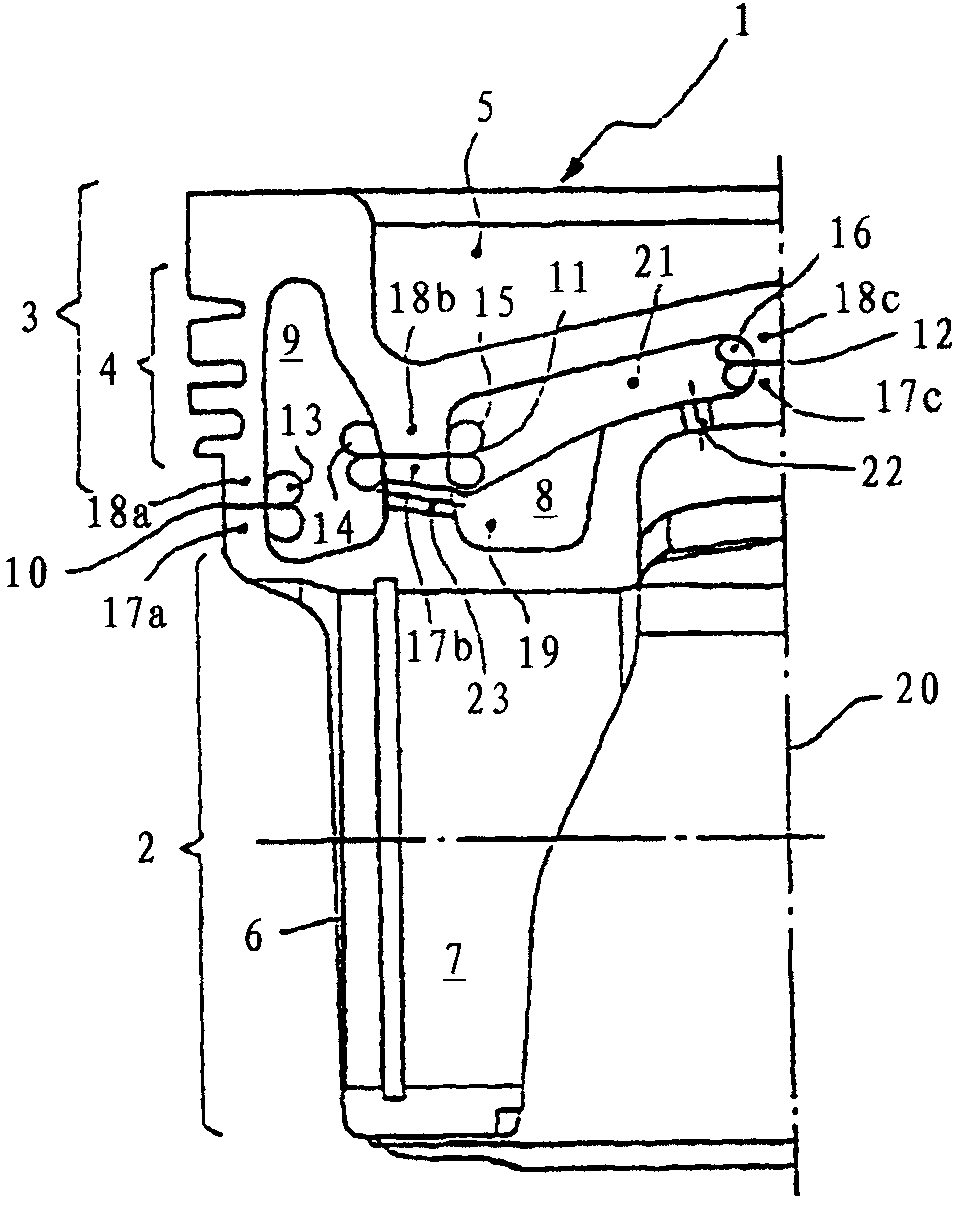
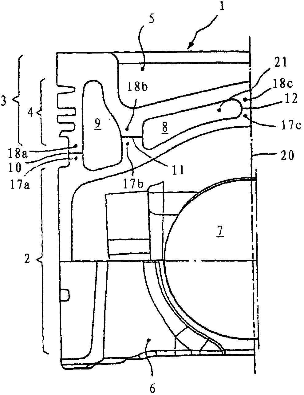
[0028] figure 1 and 2 A half-section of a piston 1 for an internal combustion engine, which is formed as a cooling channel piston and is formed from a lower part 2 and an upper part 3 , is shown in each case. Furthermore, the piston 1 comprises a ring zone 4 defined for three piston rings, a combustion chamber cavity 5 , a piston skirt and a piston pin seat bore 7 . After the lower part 2 and the upper part 3 have been joined together, the piston 1 forms an inner cooling channel 8 and an outer cooling channel 9 . At the same time, the lower part 2 and the upper part 3 are supported via joint surfaces 10 , 11 , 12 arranged offset from each other not only in the axial direction but also in the radial direction, which are joined together by means of friction welding to form composite parts, although other numbers of joint surfaces are also conceivable .

[0029]The weld clearly shows the weld projection 13 , 14 , 15 , 16 of each joint surface 10 , 11 , 12 pointing in the dire...


PUM


Abstract

The invention relates to a method for producing a piston (1) of an internal combustion engine, which is designed as a cooling channel piston for small compression heights. The piston (1) comprises a lower part (2) and an upper part (3), which are supported via one or more corresponding joint surfaces (10, 11, 12) and connected by means of friction welding. The piston (1) comprises an inner cooling channel (8) designed in the form of a groove, and an outer cooling channel (9) arranged axially at a distance from the piston ring region (4). Internal cooling channels (8) are produced in the lower part (2) of the piston (1) by machining, in particular forging. Flow openings (22, 23) arranged in cooling passages (8, 9) are produced before friction welding of joint surfaces (10, 11, 12).

Description

technical field [0001] The invention relates to a steel cooling passage piston and a manufacturing method thereof. Background technique [0002] US Pat. No. 6,155,157 discloses a cooling channel piston comprising two components which can be produced separately from one another and which are connected in a materially bonded manner via a friction welding process to form a one-piece cooling channel piston. As the cooling channel, there is provided an annular channel of narrow dimensions that is spaced from the piston ring region of the piston and surrounds it, and opens in the direction of the inner contour of the piston via inflow and outflow bores. The cooling channel is fed with coolant, in particular oil, via a fixedly positioned nozzle. Such cooling channels, which can be implemented relatively easily, do not allow sufficient cooling of the piston at local points. Contents of the invention [0003] Starting from the known state of the art, the object of the present inv...

Claims


Application Information

Patent Timeline
Patent Type & Authority Patents(China)
IPC IPC(8): B23P15/10F02F3/00F02F3/22F16J1/09B21K1/18
CPCB23K2201/003B23K20/12B23P15/10F02F3/003B21K1/18F02F3/22B21K1/185B23K2101/003Y10T29/49256
Inventor V·格尼斯默N·里斯
Owner KOLBENSCHMIDT AG
Why Eureka
Try Eureka