

Light transmit-receive integrated module for myriad million light line terminal
A line terminal, optical transceiver technology, applied in the field of optical communication, can solve the problems affecting the use requirements of the optical network system, and achieve the effects of reducing the difficulty of production, increasing the convenience of disassembly, and increasing the flexibility
Inactive Publication Date: 2009-02-25
HISENSE BROADBAND MULTIMEDIA TECH
View PDF0 Cites 19 Cited by
- Summary
- Abstract
- Description
- Claims
- Application Information
AI Technical Summary
Problems solved by technology
However, with the increase in the number of optical network units connected to optical line terminals and the continuous increase in bandwidth requirements of optical network unit end users, the downlink bandwidth provided by the existing optical line terminal optical transceiver module has seriously affected the optical network system. The use requirements of the system cannot well meet people's needs for video signal clarity and other data transmission speeds
Method used
View moreImage
Smart ImageViewing Examples

Examples
Embodiment Construction
Login to View More PUM
 Abstract
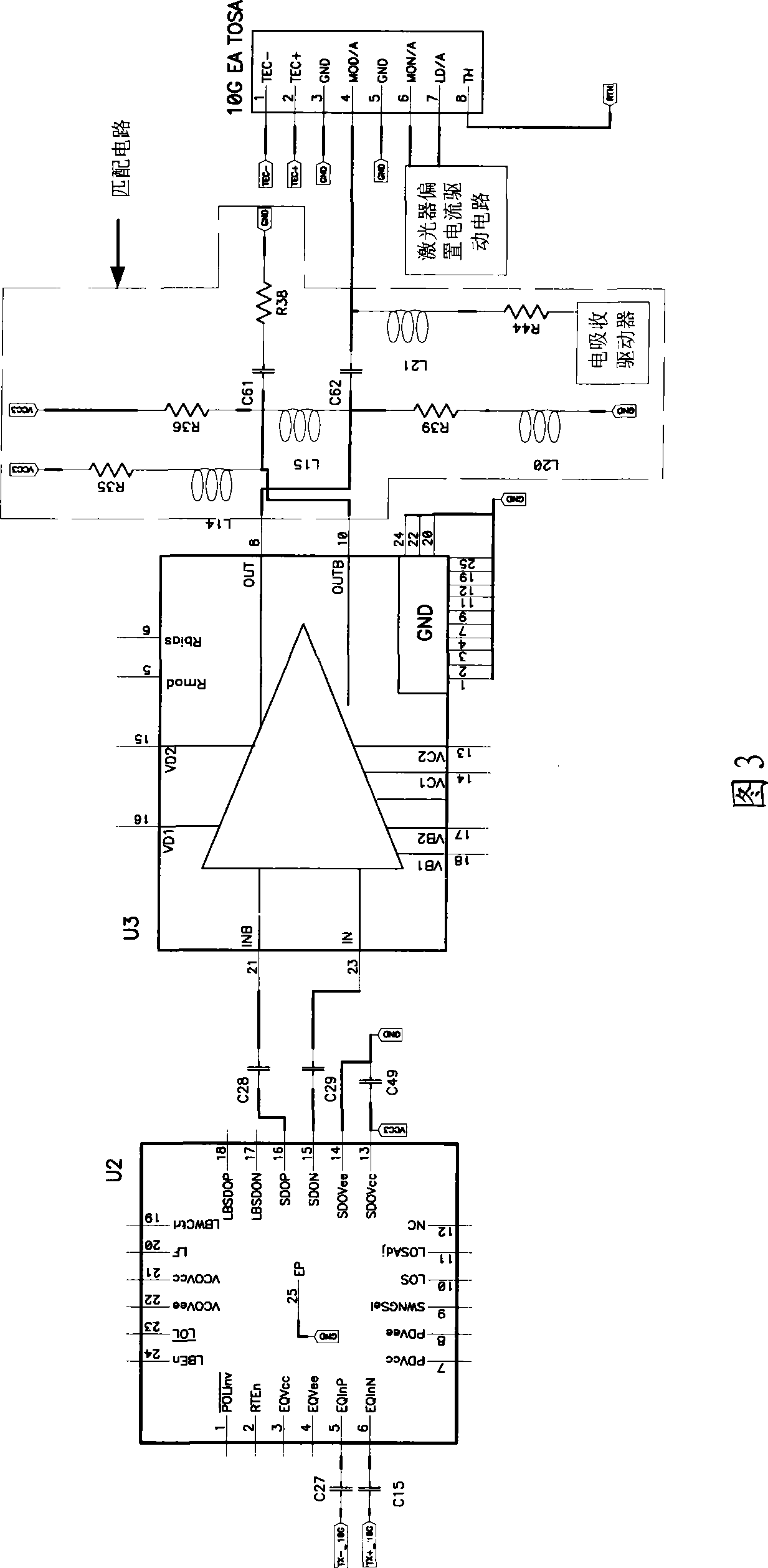
The invention discloses a 10 Giga optical link terminal optical transmitter and receiver integrated module, which includes a module optical interface, a module electrical interface and a kilo mega transmitter and receiver integrated optical component, also includes a 10 Giga optical transmitter component, and a 10 Giga transmitter drive circuit for driving the component. The 10 Giga transmitter drive circuit is composed of a signal transformation circuit, a laser drive circuit and a matching circuit, wherein the signal transformation circuit input terminal is connected with the electrical signal to be transmitted, the signal after being transformed by the signal transformation circuit is inputted into the laser drive circuit, the modulated signal, which is outputted from the laser drive circuit and is modulated by the matching circuit, is inputted into the electroabsorption modulator input terminal of the 10 Giga optical transmitter component, for driving 10 Giga optical transmitter component transmitter emitted light signal. The optical receiver and transmitter integrated module has signals with 10Gbps and 1.25Gbps down transmission rate, and signals with 1.25Gbps upward transmission rate, thereby realizing asymmetric transmission of upward signal and down signal for meeting the need of high-speed bandwidth.
Description
technical field The invention relates to an integrated optical transceiver module, in particular to a 10 Gigabit optical transceiver integrated module used by an optical line terminal of an Ethernet passive optical network, and belongs to the technical field of optical communication. Background technique With the continuous development of optical communication technology, more and more video services and interactive services such as video calls, conference calls, online interactive games, video-on-demand, and high-definition TVs have entered thousands of households. Multi-services are the future of broadband development. The main direction. With the continuous development of broadband multi-services, there are higher requirements for network bandwidth. At present, Ethernet passive optical network (EPON) optical transceiver module for FTTx services such as fiber-to-the-curb (FTTC), fiber-to-the-building (FTTB) and fiber-to-the-home (FTTH) contains a gigabit transceiver integ...
Claims
Login to View More Application Information
Patent Timeline
 IPC IPC(8): H04Q11/00H04B10/14H04B10/12G02B6/42G02B6/38H04B10/40
Inventor赵其圣杨思更何鹏张强
OwnerHISENSE BROADBAND MULTIMEDIA TECH