
Control method of roll forming of twin-roll thin strip continuous casting cooling roll

A technology of twin-roll thin strip continuous casting and control method is applied in the field of continuous casting technology and equipment in the metallurgical industry, and can solve the problems of the adverse effects of cooling roll sleeves and surface coatings, reducing the service life of cooling rolls, and increasing strip thickness tolerances. , to achieve the effect of reducing the workload of trimming and leveling, prolonging the service life, and limiting the change of the roll shape.

Active Publication Date: 2011-04-13
BAOSHAN IRON & STEEL CO LTD
View PDF16 Cites 2 Cited by
  • Summary
  • Abstract
  • Description
  • Claims
  • Application Information

AI Technical Summary

Problems solved by technology

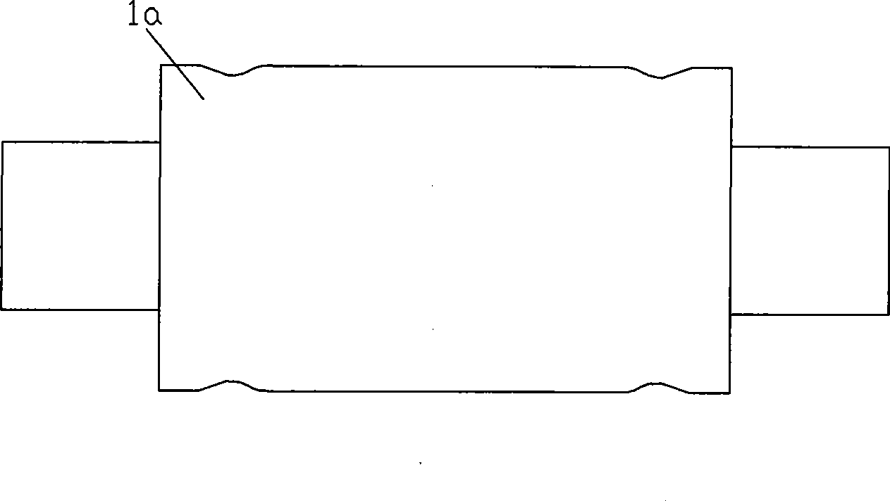
[0009] And find in actual test research, if just simply make the roll surface cool evenly, as the cooling roll described in CN03231727.1, the deformation of the roll surface during its work causes the roll surface to be uneven, as figure 2 As shown, especially at the water ring, due to the high cooling intensity, the thickness of the local strip cross-section will be thicker, resulting in increased strip thickness tolerance, which is not conducive to the subsequent rolling treatment; in addition, because the entire cooling roll is in different temperature gradients In this case, it is easy to produce local stress concentration, which will adversely affect the cooling roll sleeve and surface coating, and reduce the service life of the cooling roll
Another example is the cooling roll structure mentioned in the patent US6241002, CN1234304A, which will produce the edge defects of the strip as mentioned above due to the influence of the side sealing plate

Method used


Image

  • Control method of roll forming of twin-roll thin strip continuous casting cooling roll
  • Control method of roll forming of twin-roll thin strip continuous casting cooling roll
  • Control method of roll forming of twin-roll thin strip continuous casting cooling roll

Examples


Embodiment Construction

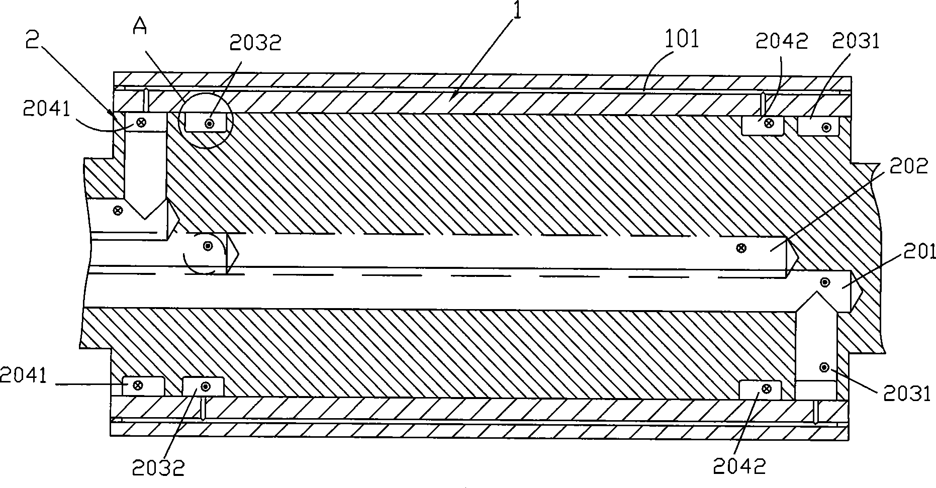
[0058] see image 3 , Figure 4 , which is an embodiment of the present invention. In this embodiment, two cooling rolls that pass through cooling water in relative rotation, including the roll sleeve 1 and the roll shaft 2, are shrink-fitted together, and the roll sleeve 1 adopts Made of special materials, it has good thermal conductivity and resistance to shock and heat; the roller shaft 2 is made of high-strength structural steel, and the shape of the cooling roller is a cylindrical flat roller. A water channel 101, a water inlet channel 201 and a water outlet channel 202 are opened in the axial direction of the roller shaft 2, and two cooling water channels corresponding to the water inlet and outlet channels 201, 202 and the roller sleeve 1 are respectively opened on both sides of the outer periphery 101 is connected to the water inlet water collection ring groove 2031, 2041 and the water outlet water collection ring groove 2032, 2042; the inner peripheral edge of the ro...


PUM

PropertyMeasurementUnit
thicknessaaaaaaaaaa
thermal conductivityaaaaaaaaaa

Abstract

The invention discloses a method for controlling a roll shape of a double-roll thin-strip continuous-casting and cooling roll. The double-roll thin-strip continuous-casting adopts a cooling roll connected with cooling water; the cooling roll comprises a roll sleeve and a roll shaft; a cooling water channel is formed in the roll sleeve and used for water flowing; a water input and output channel is axially formed in the roll shaft, and at least two water collecting ring grooves which are connected with the water input and output channel and the cooling water channel in the roll sleeve are formed on two sides of the outer circumference thereof; the inner wall of the inner circumference of the roll sleeve corresponding to the water collecting ring groove of the roll shaft is coated with a layer of heat resistance material; and the thermal conductivity of the heat resistance material is smaller than that of the roll sleeve material. The method can facilitate the cooling uniformity of the inside of the cooling roll sleeve and the roll surface by adding the coating for the water collecting ring grooves inside the cooling roll sleeve, thereby avoiding the partial thermal expansion inconformity resulted from the uneven heat transmission, and avoiding the damage to the surface coatings of the cooling roll sleeve and the cooling roll resulted from the partial thermal stress generated bythe partial thermal expansion inconformity. The device can improve the service life of the cooling roll and acquire casting strips with good quality and strip shape.

Description

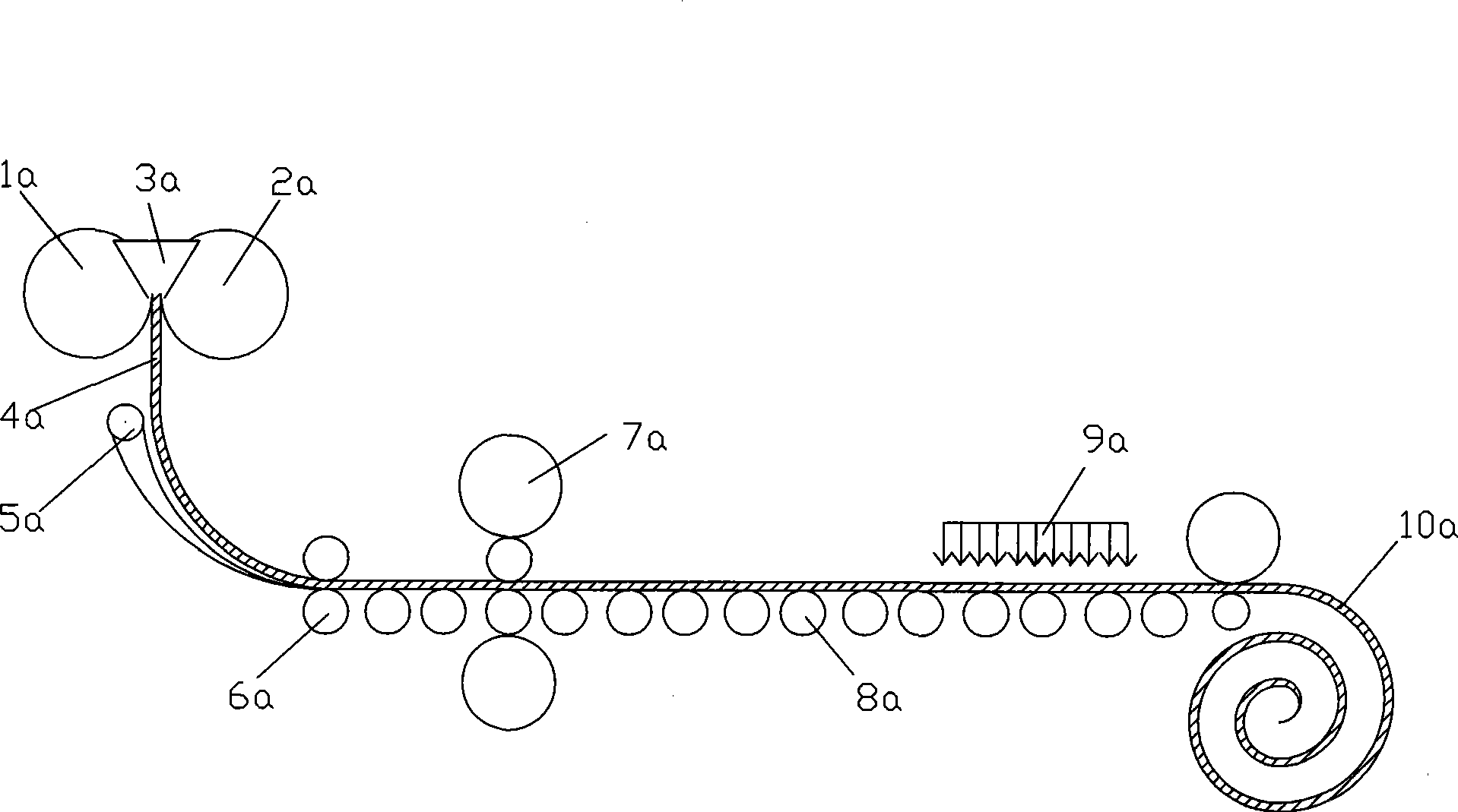
technical field [0001] The invention relates to a continuous casting process and equipment technology in the metallurgical industry, in particular to a method for controlling the roll shape of a twin-roll strip continuous casting cooling roll. Background technique [0002] The development of twin-roll thin strip continuous casting technology has a history of 150 years, and it belongs to the category of sub-rapid cooling continuous casting process. Typical examples are figure 1 As shown, the molten steel is directly poured in a molten pool surrounded by two relatively rotating and rapidly cooling cooling rolls 1a, 2a and side sealing device 3a, and the molten steel is cooled and solidified on the circumferential surface of the cooling roll rotation, Then a solidified shell is formed and gradually grows, and then squeezed together at the smallest gap between the two cooling rollers 1a and 2a, and finally forms a thin metal strip 4a with a thickness of 1-5mm at the strip outlet...

Claims


Application Information

Patent Timeline
Patent Type & Authority Patents(China)
IPC IPC(8): B22D11/055B22D11/06
Inventor 王成全叶长宏田守信于艳方园
Owner BAOSHAN IRON & STEEL CO LTD
Learn More