Hydrogen and oxygen electrolyzing device and fuel-saving automobile
A hydrogen-oxygen and electrolyzer technology, applied in the direction of electrolysis process, electrolysis components, power devices, etc., can solve the problems of polluting the natural environment, low fuel combustion rate, high fuel consumption, etc., achieve good results, increase oxygen content, and consume The effect of reducing the amount of oil
- Summary
- Abstract
- Description
- Claims
- Application Information
AI Technical Summary
Problems solved by technology
Method used
Image

Examples
specific Embodiment
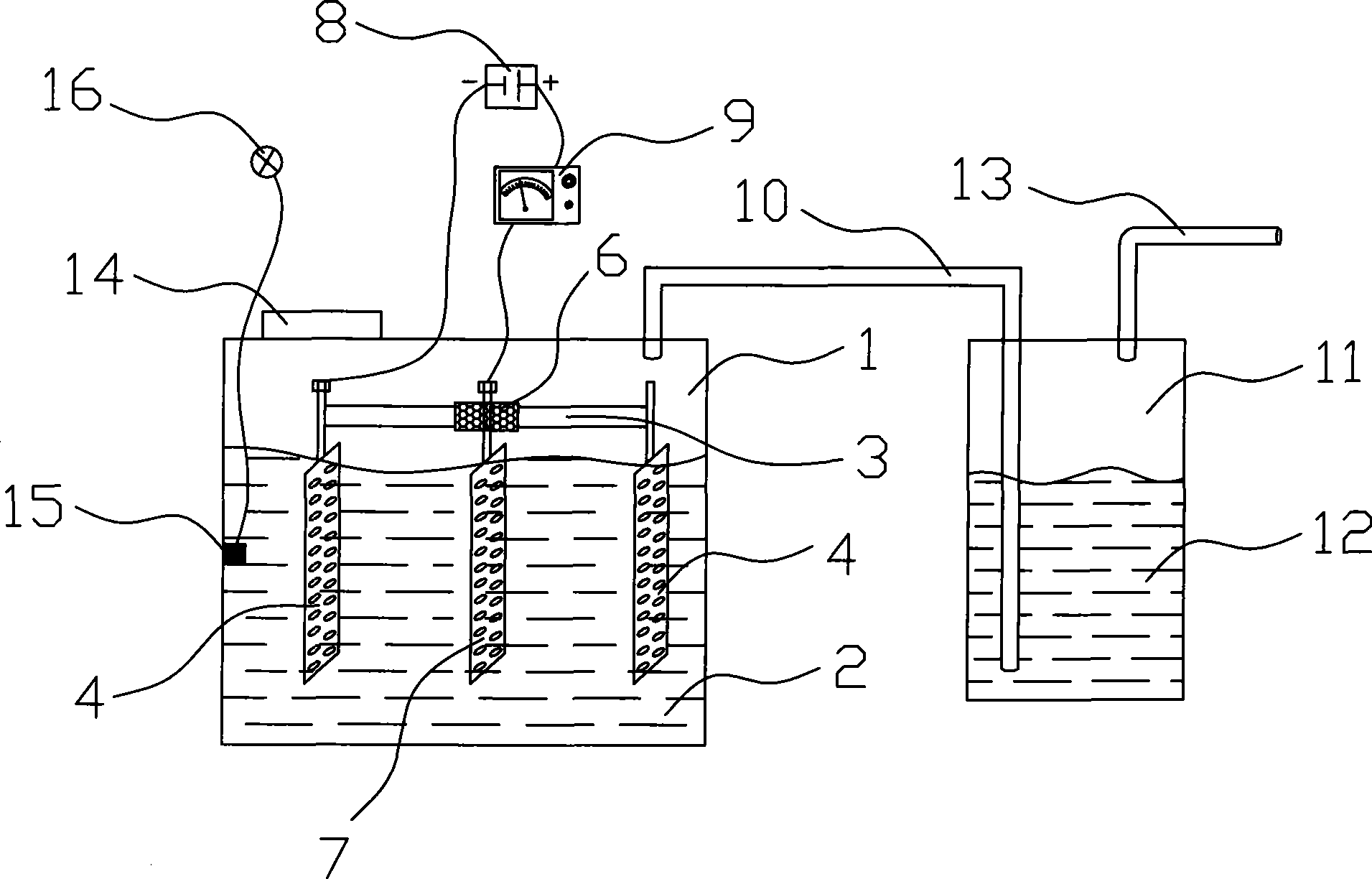
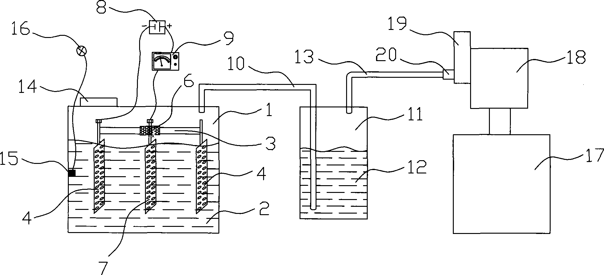
[0019] Such as figure 1 As shown, a device for electrolyzing hydrogen and oxygen includes a DC power supply 8, an electrolytic cell 1, and positive and negative electrode sheets arranged in the electrolytic cell 1;
[0020] Wherein, the positive and negative electrode sheets are respectively connected to the positive and negative poles of the DC power supply 8, and the electrolytic cell 1 is a sealed electrolytic cell; the positive electrode sheet 7 has one sheet, and the negative electrode sheet 4 has two sheets, two sheets The negative electrode sheet 4 is arranged at both ends of a conductive rod 3, and the two negative electrode sheets 4 are conducted through the conductive rod 3, and the middle part of the conductive rod 3 is provided with an insulating porcelain sleeve 6, and the insulating porcelain sleeve 6 The positive electrode sheet 7 is fixed on the sleeve 6; the positive and negative electrode sheets are made of stainless alloy, which are in a mesh structure, arra...
PUM
 Abstract
Description
Claims
Application Information
PatSnap Eureka turns technology decisions into work you can execute. Powered by our Innovation Knowledge Graph, it runs expert workflows across engineering, life sciences, materials and intellectual property. Get your review-ready output in minutes.


