
Linear array CCD on-road vehicle speed measuring method based on instant hardware technology

A vehicle and line array technology, which is applied in the traffic control system of road vehicles, the device for measuring the time required to move a certain distance, and the radio wave measurement system, etc. Expensive and other issues, to achieve the effect of concealed speed measurement capability, stable performance, and low cost

Inactive Publication Date: 2009-03-11
ANHUI HONGSHI OPTOELECTRONICS HIGH TECH CO LTD
View PDF0 Cites 7 Cited by
  • Summary
  • Abstract
  • Description
  • Claims
  • Application Information

AI Technical Summary

Problems solved by technology

The Doppler radar speed measurement system is widely used, but it is susceptible to external interference, and the speed measurement accuracy is not high. At the same time, the Doppler speed measurement system needs to emit radar waves to measure speed. With the proliferation of electronic dogs, the radar speed measurement system is easy to be detected. arrive
The laser speed measurement system has high precision and good stability, but it is greatly affected by the environment, and the price is much more expensive than the general speed measurement system, so it is not easy to popularize and use
The induction coil speed measurement needs to embed the coil under the road surface, the construction and installation are complicated, and it is not easy to promote
At present, the radar speed measurement system is widely used by the traffic police department, but the electronic dog can detect the radar waves emitted by the speed measurement system, which can let the violating vehicle know that it is being measured in advance, so that the violating vehicle often escapes legal sanctions
Therefore, the radar speed measurement system is facing the challenge of the electronic dog

Method used


Image

  • Linear array CCD on-road vehicle speed measuring method based on instant hardware technology
  • Linear array CCD on-road vehicle speed measuring method based on instant hardware technology
  • Linear array CCD on-road vehicle speed measuring method based on instant hardware technology

Examples


Embodiment Construction

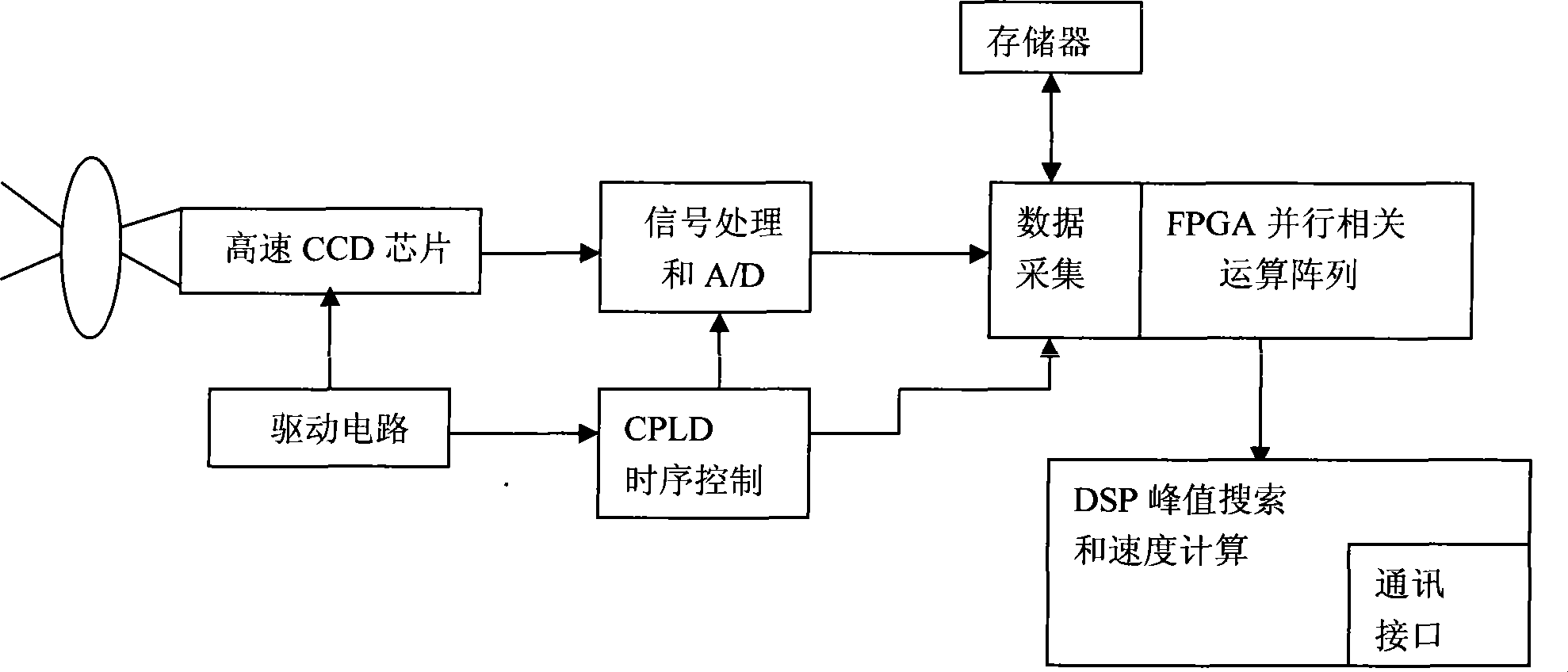
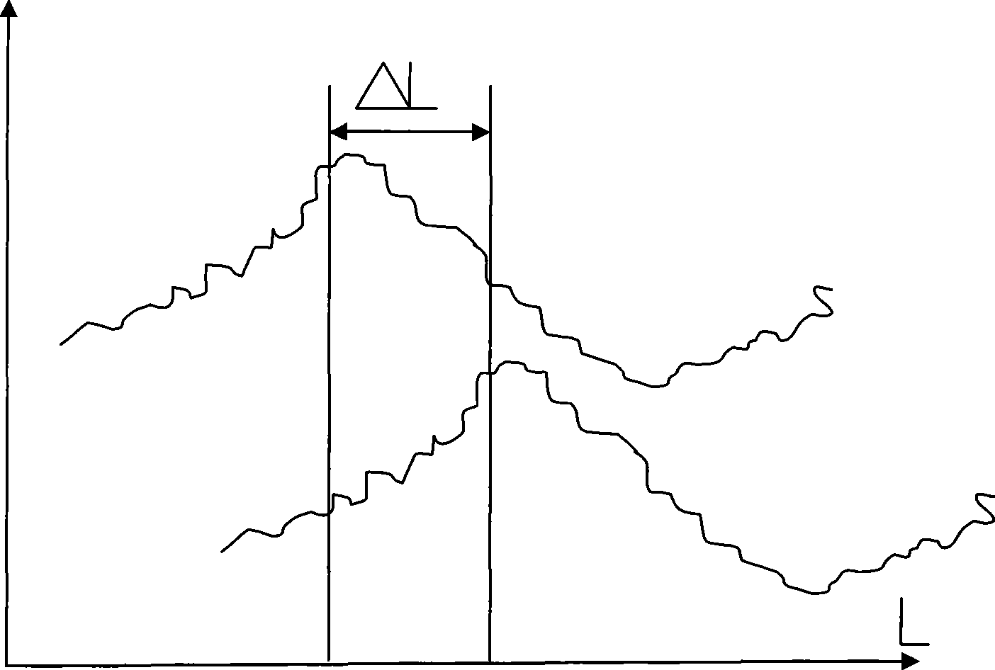
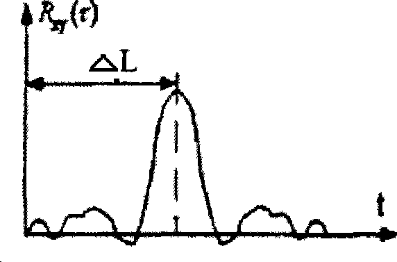
[0013] A speed measurement method of a linear array CCD road speed measurement system based on instantaneous hardware technology. A linear array CCD camera is set up on the road, and the vehicle images are taken at a certain time interval for vehicles driving on the road, and two groups of images of vehicles at different times are obtained. Image signal sequence, calculate the distance that the two sets of image signal sequences have moved on the linear array CCD, and calculate the moving speed of the image from the known time difference between the two moments, according to the distance between the linear array CCD camera and the vehicle and the linear array The parameters of the CCD camera can finally determine the speed of the vehicle. The calculation of the distance moved by the two groups of image signal sequences on the linear array CCD is to calculate the cross-correlation function and auto-correlation function of the two groups of image signals, and obtain the differenc...


PUM


Abstract

The invention discloses a velocity testing method for road vehicles, which is based on a linear array CCD (Charge Coupled Device) of instantaneous hardware. A linear array CCD video camera is erected on road. Aiming at a vehicle running on the road, photos are taken at a certain interval of time so as to obtain two groups of image signal sequences of the vehicle at different moments, and the displacement distances of the two groups of image signal sequences on the linear array CCD are calculated; based on the time difference of the two known moments, an image displacement velocity is calculated, and the movement velocity of the vehicle can be finally calculated according to the distance between the linear array CCD video camera and the vehicle and the parameters of the linear array CCD video camera. The invention has stable performance, higher accuracy and lower cost without being influenced by terrain and externally transmitting radar waves, thereby being hard to be detected by an electronic dog and having a favorable hidden velocity testing capability.

Description

technical field [0001] The invention relates to a road vehicle speed measurement method, in particular to a linear array CCD road vehicle speed measurement method based on instantaneous hardware technology. Background technique [0002] At present, there are mainly the following types of vehicle speed measurement systems: Doppler radar speed measurement system, laser speed measurement system and induction coil speed measurement system. The Doppler radar speed measurement system is widely used, but it is susceptible to external interference, and the speed measurement accuracy is not high. At the same time, the Doppler speed measurement system needs to emit radar waves to measure speed. With the proliferation of electronic dogs, the radar speed measurement system is easy to be detected. arrive. The laser speed measurement system has high precision and good stability, but it is greatly affected by the environment, and the price is much more expensive than the general speed mea...

Claims


Application Information

Patent Timeline
Patent Type & Authority Applications(China)
IPC IPC(8): G08G1/054G01P3/68
Inventor 王世勇赵吉文徐道际路巍查世红
Owner ANHUI HONGSHI OPTOELECTRONICS HIGH TECH CO LTD
Learn More