Polishing technique of ring stainless steel precise parts and preparation method thereof

A technology of precision parts and stainless steel, applied in the field of polishing, can solve problems such as inability to meet requirements, low work efficiency, damage, etc., and achieve the effects of good polishing effect, easy operation and low cost

Inactive Publication Date: 2009-03-18
江苏星河集团有限公司 +1
View PDF0 Cites 6 Cited by
  • Summary
  • Abstract
  • Description
  • Claims
  • Application Information

AI Technical Summary

Problems solved by technology

There are many common polishing methods. One is to use chemical or electrolytic polishing methods. Due to chemical or electrolytic effects, a certain amount of corrosion is caused to the surface of the polished part. The general corrosion amount is 0.03 to 0.08 mm. The hardness layer is corroded; the second is to adopt m

Method used


Image

  • Polishing technique of ring stainless steel precise parts and preparation method thereof
  • Polishing technique of ring stainless steel precise parts and preparation method thereof
  • Polishing technique of ring stainless steel precise parts and preparation method thereof

Examples


Embodiment 1

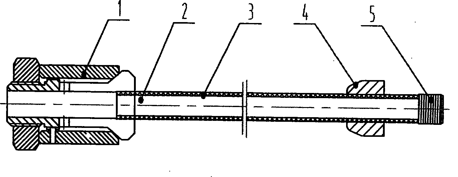
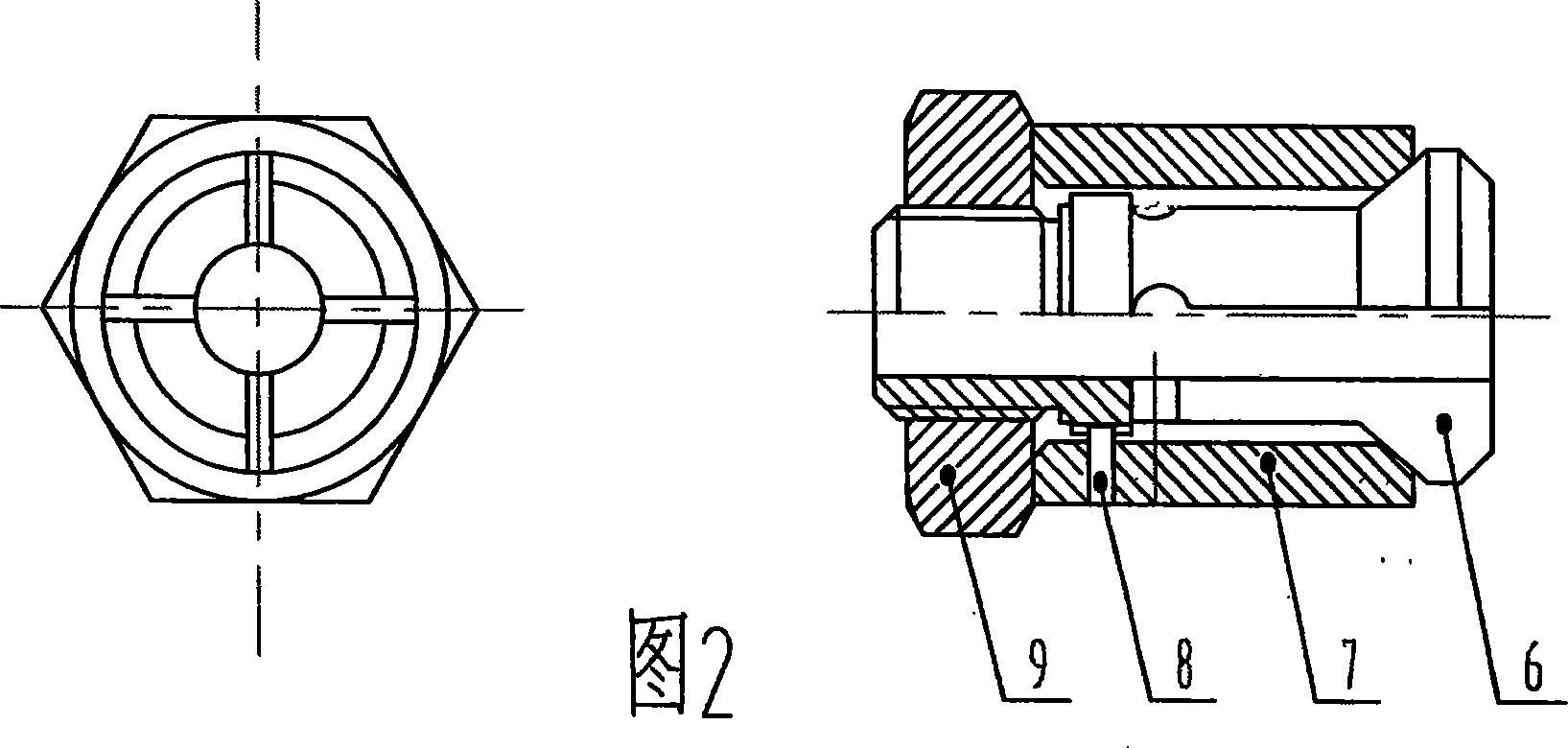
[0031] Degrease the surface of the polished part (11), ultrasonically clean it in an aqueous solution of detergent for about 10 minutes, rinse it with clean water, and then dry it. Fix the polishing machine equipped with a soft cloth polishing wheel (12) on the frame, use a metal circle whose diameter is 2 to 4 mm less than the inner diameter of the polished part and whose length is 25 to 40 times the inner diameter of the polished part (11) Rod (2), and a cloth tape (3) are evenly and tightly wound in a clockwise direction from one end of the metal round rod (2) to the other end, and the tape is tightened by the tensioner (1) at the beginning (3) is clamped with the metal round rod (2), and the other end is fastened and fixed with the cloth tape (3) and the metal round rod (2) with a thin wire (5) to form a polishing rod assembly (such as figure 1 shown); the tightener (1), as shown in Figure 2, puts the collet (6) in the jacket (7), and a limited rotation positioning Xiao (8...

Embodiment 2

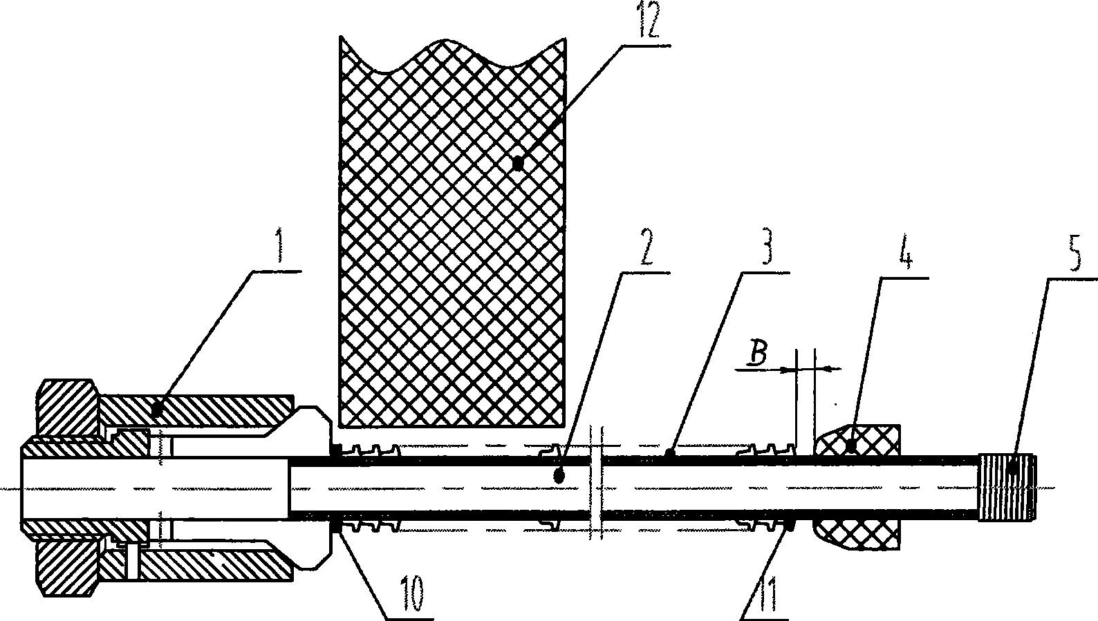
[0034] Difference with embodiment 1 is: if the endoporus of polished part (11) has groove shape structure, as Figure 5 As shown in B, in order to make the inner hole groove polished to the same effect as other parts, the cloth tape (3) wrapped on the metal round rod (2) adopts a thicker material, such as woolen or woolen Due to the certain thickness of the blended cloth tape, the wound polishing rod is more plump and elastic, which is more conducive to polishing the inner groove of the inner hole. Use a metal round rod (2) with a diameter smaller than the inner diameter of the part to be polished by 3 to 5 mm and a length of 20 to 35 times the inner diameter of the part to be polished (11), and a cloth tape (3) from the metal round rod (2) One end to the other end is spirally wound evenly and evenly in a clockwise direction, the starting end is clamped by the tensioner (1) with the cloth tape (3) and the metal round rod (2), and the other end is the cotton tape (3) ) is fast...


PUM

PropertyMeasurementUnit
The inside diameter ofaaaaaaaaaa

Abstract

The invention provides a polishing technique of an annular stainless steel precision component and a preparation method thereof, which is applied to the machine building industry and can obtain a surface with higher brightness and maintain necessary acute angles on the premise of not affecting the size precision of the component. The polishing technique and the preparation method are characterized in that: a strap is used for closely and evenly wrapping from one end of a round metal bar to the other end thereof in a clockwise manner; the beginning end of the strap is clamped with the round metal bar by a tightener, while the other end thereof is fastened and fixed with the round metal bar by a fine line, thus forming a polishing bar with a surface evenly coated with polishing wax; a plurality of components to be polished are sheathed on the polishing bars and then a stop collar is arranged; the tightener is held by the left hand, and the stop collar and the end of the polishing bar are grabbed by the right hand; the components to be polished are slowly and horizontally moved to get close to the excircle of a soft cloth polishing wheel with rotates at a high speed and is coated with polishing wax; force is gradually increased, and the components to be polished between the tightener and the stop collar are moved back and forth until the components to be polished meet polishing requirements.

Description

Technical field: [0001] The invention relates to a polishing technology in mechanical processing, in particular to a process method for surface polishing of a small circular stainless steel precision part, which achieves a bright surface and maintains a necessary acute angle without affecting the dimensional accuracy of the part. Background technique: [0002] In order to improve the performance or appearance quality of the products, many precision parts of small circular stainless steel need to be polished to obtain higher surface roughness and brightness without affecting the dimensional accuracy of the original parts. For example, the rear ferrule, an important part of the stainless steel double ferrule pipe joint, is a typical case. It needs to obtain a surface hardness layer through heat treatment (the thickness of the hard layer is only 0.025-0.05mm). Excellent surface roughness and brightness, but also maintain a sharper edge (acute angle). Polishing is required due ...

Claims


Application Information

Patent Timeline
IPC IPC(8): B24B19/11B24B29/02B24B55/00
Inventor 朱义芳
Owner 江苏星河集团有限公司
Why Eureka
Try Eureka