Push cam type internal combustion engine without side pressure

An internal combustion engine, cam-type technology, applied in mechanical equipment, engine components, machines/engines, etc., can solve problems such as aggravating cylinder wall, piston wear, large pressure axial force, vibration and noise, complex mechanism, etc., to eliminate friction and wear and The effect of friction power consumption, improving work efficiency and simplifying the valve train

Inactive Publication Date: 2009-03-18
SICHUAN UNIV
View PDF0 Cites 6 Cited by
  • Summary
  • Abstract
  • Description
  • Claims
  • Application Information

AI Technical Summary

Problems solved by technology

[0003] First: Since the movement of the connecting rod is a periodic plane movement, a large periodical alternating side pressure is generated between the piston and the cylinder wall, thereby aggravating the wear of the cylinder wall and piston (piston ring), shortening the life of the internal combustion engine, and aggravating Wear consumes more power than normal, making the transmission of the internal combustion engine less efficient
[0004] Second: Due to the eccentricity of the mass of the crankshaft and other parts, the planar movement of the connecting rod group, and the unbalanced force of the parts, etc., resulting in a large final shaft force, vibration and noise
In addition, in order to make the intake valve and exhaust valve open and close in a timely manner, a valve timing mechanism is usually used, which makes the internal combustion engine have a large number of parts, a complicated mechanism, a large and heavy
[0006] Fourth: The structure of the crankshaft is complex and difficult to manufacture

Method used


Image

  • Push cam type internal combustion engine without side pressure
  • Push cam type internal combustion engine without side pressure
  • Push cam type internal combustion engine without side pressure

Examples


Embodiment 1

[0035] Embodiment 1: Four-phase cam four-cylinder internal combustion engine

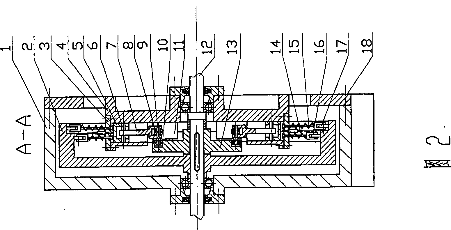
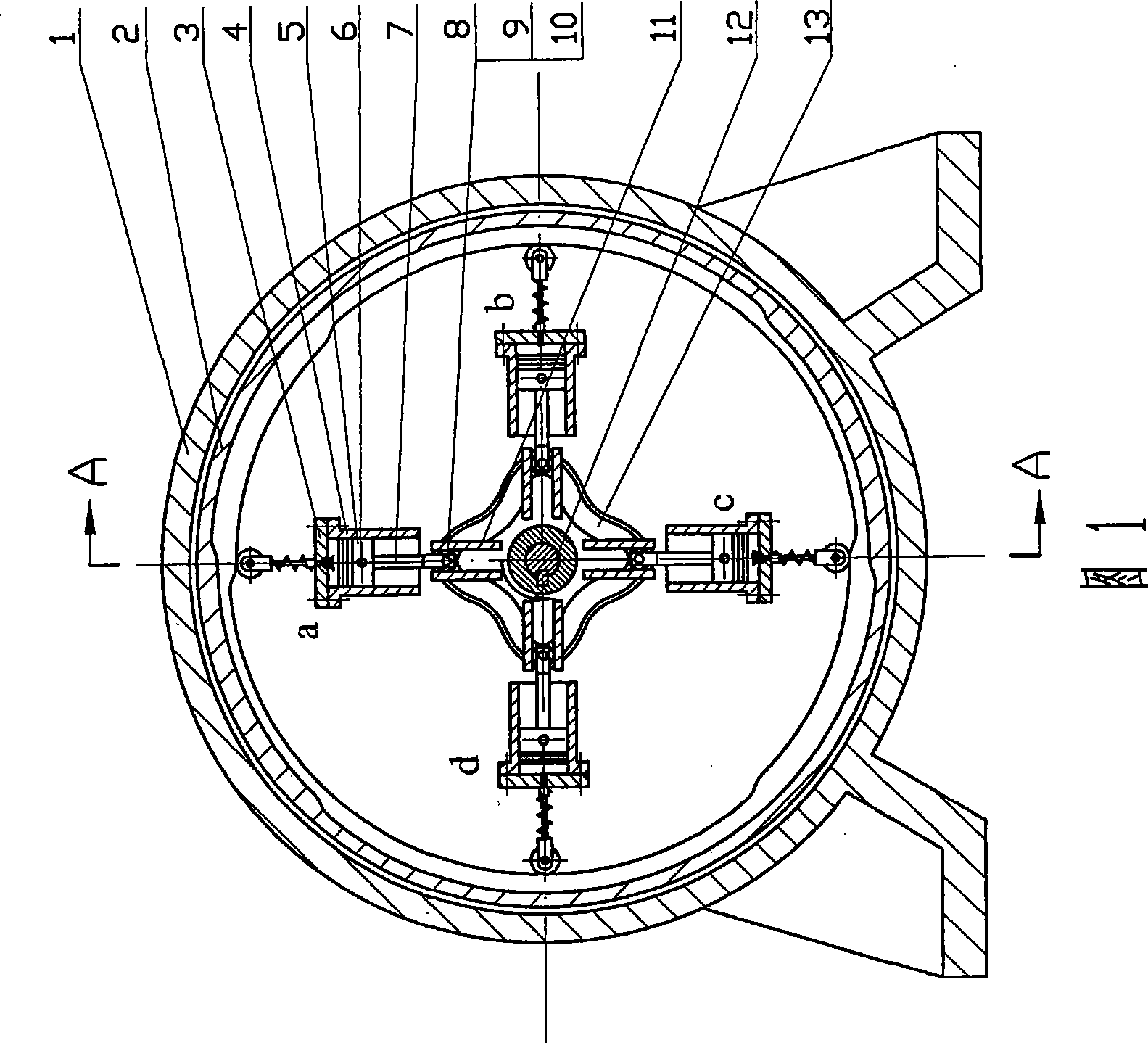
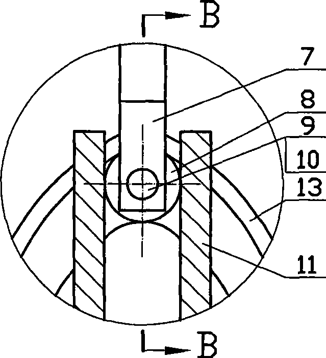
[0036] Refer to attached picture 1~ Image 6 : In Figure 1~ Figure 4 In the shown four-phase cam four-cylinder internal combustion engine, the main shaft (12) is supported by two left and right bearings, and the four cylinders (4) are symmetrically distributed around the main shaft (12), and the angle between two adjacent cylinders is 90 °, and each cylinder is integrated with the frame (18) (the cylinder can also be manufactured separately, and then it is fixed on the frame with pins and bolts). Air vents are arranged on the frame, and the frame and the machine base (1) are fixedly connected together with bolts. One end of the push rod (7) is hinged with the piston (5) through the piston pin (6), and the other end is fixed with a push rod pin (9), on which a push rod roller (8) and a cam are mounted. rollers (10). 4 guide grooves (11) produced on the frame (18) are also axisymmetrically evenly...

Embodiment 2

[0038] Embodiment 2: Four-phase cam eight-cylinder internal combustion engine

[0039] refer to Figure 7 and Figure 2~ Image 6 :exist Figure 7 and Figure 2~ Figure 4 In the shown four-phase cam eight-cylinder internal combustion engine, eight cylinders (4) and eight guide grooves (11) are evenly distributed on the periphery of the main shaft (12) in axisymmetric manner, and the angle between two adjacent cylinders is 45° , the symmetry line of the guide groove (11) coincides with the axis line of the cylinder (4), and the shape, structure, connection relationship and working principle of each component are similar to those of a four-phase cam four-cylinder internal combustion engine, so the distance between the piston and the cylinder wall The lateral pressure between them is zero. exist Figure 7 Among them, the pistons in cylinders a, c, e, and g are at the farthest position from the axis, that is, the top dead center position, while the pistons in cylinders b, d, f, a...

Embodiment 3

[0041] Embodiment 3: Six-phase cam six-cylinder internal combustion engine

[0042] Refer to Figure 8~ Figure 11 and Figure 3 ~ Figure 4 : In Figure 8~ Figure 11 and Figure 3 ~ Figure 4 In the shown six-phase cam six-cylinder internal combustion engine, six cylinders (4) and six guide grooves (11) are evenly distributed on the periphery of the main shaft (12) axisymmetrically, and the angle between two adjacent cylinders is 60° , the line of symmetry of the guide groove (11) coincides with the axis line of the cylinder (4), the cylinder (5) and the guide groove (11) are integrated with the frame (18), and can also be fixedly connected to the frame after being manufactured separately superior. The main cam (13) has six axially symmetrical protrusions, and each two protrusions form an angle of 60 °; the main cam also has a cam-shaped groove. The contour curve of the cam-shaped groove on the main cam can select different curves as required. In this embodiment, the conto...


PUM


Abstract

The invention relates to a non-side pressure push rod cam combustion engine, which transmits power of pistons to a main cam fixed on a main shaft by a push rod for output, wherein one end of the push rod is connected with hinges of the pistons, and the other end of the push rod is provided with a cam roller and a push rod roller; the cam roller is inserted into a cam-shaped groove on the main cam; the push rod roller is arranged inside a guide groove, so as to drive the push rod to move along the guide groove and make the guide groove bear the circumferential component force of the acting force of the main cam on the push rod, thereby the side pressure between the pistons and the cylinder walls is zero; cylinders are uniformly distributed on the circumference of the main cam and symmetrical with the axle center of the main cam; the acting force of all the pistons on the main cam is completely balanced; and a duplex inner cam which is fixed on the main shaft is used for controlling inlet valves and exhaust valves of all the cylinders. Compared with the prior combustion engine, the non-side pressure push rod cam combustion engine saves a crank-link mechanism, a distribution timing gear mechanism and so on, and has the characteristics of simple structure, small axial dimension, no side pressure, small abrasion, long service life, low vibration and noise, stable operation, large power, high transmission efficiency and so on.

Description

technical field [0001] The invention relates to the reciprocating internal combustion engine technology, in particular to the internal combustion engine technology which converts the reciprocating motion of the cylinder piston of the internal combustion engine into the rotary motion of the power output main shaft. Background technique [0002] Existing reciprocating four-stroke internal-combustion engine utilizes the crank-link mechanism to convert the reciprocating linear motion of the piston into the rotary motion of the crankshaft to output motion and power. There is following defective in the internal combustion engine of this structure type: [0003] First: Since the movement of the connecting rod is a periodic plane movement, a large periodical alternating side pressure is generated between the piston and the cylinder wall, thereby aggravating the wear of the cylinder wall and piston (piston ring), shortening the life of the internal combustion engine, and aggravating ...

Claims


Application Information

Patent Timeline
IPC IPC(8): F01L1/06F01L1/26
Inventor 梁尚明
Owner SICHUAN UNIV
Why Eureka
Try Eureka