Desulfurization dust collector for industrial furnace

A technology for desulfurization and dust removal, industrial furnaces and kilns, which is applied in the field of atmospheric environmental protection equipment, can solve the problems of large investment in dust collectors, high power consumption, and the inability of small and medium foundry enterprises to bear the cost of dust removal, and achieves the effects of high dust removal efficiency and long contact time.

Inactive Publication Date: 2009-03-25
姚立猛
View PDF0 Cites 7 Cited by
  • Summary
  • Abstract
  • Description
  • Claims
  • Application Information

AI Technical Summary

Problems solved by technology

This type of dust removal device can remove harmful particles in the cupola flue gas and eliminate some harmful gases in the flue gas, but this type of dust collector has a large investment, high power consumption, and high operating costs
[0007] As mentioned above, the current dedusting devices used for cupola furnaces or the dedusting effect cannot meet the national emission standards, or the investment is large and the operating cost is high, and small and medium-sized foundries cannot afford the dedusting cost.

Method used


Image

  • Desulfurization dust collector for industrial furnace
  • Desulfurization dust collector for industrial furnace
  • Desulfurization dust collector for industrial furnace

Examples


Embodiment 1

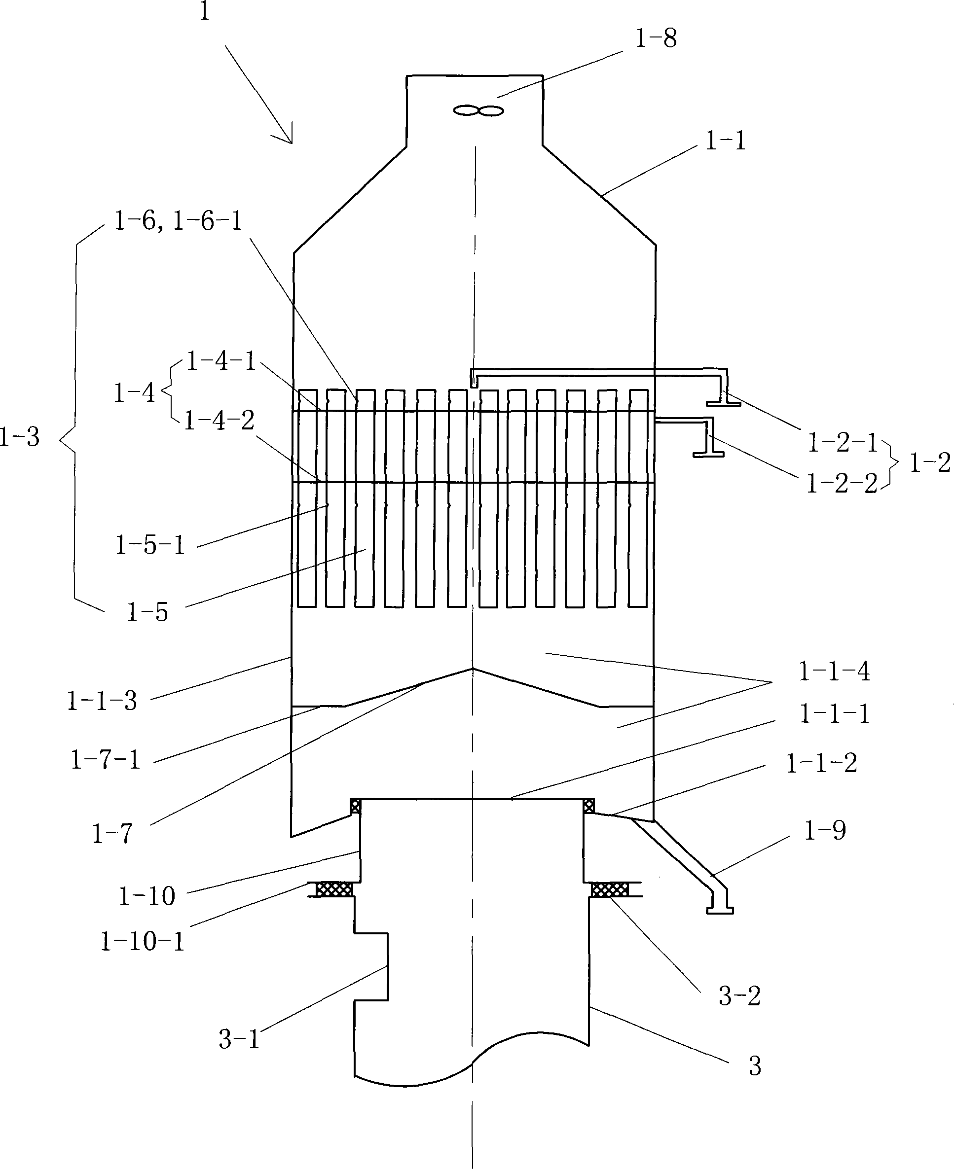
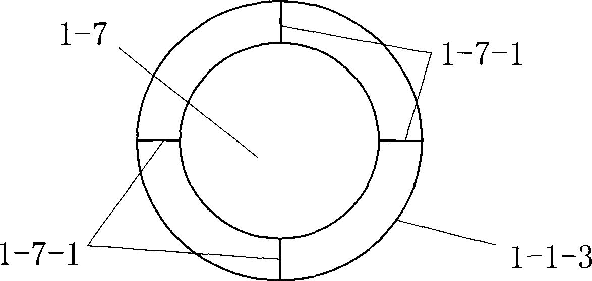
[0064] See figure 1 The desulfurization and dust removal device for industrial furnaces in this embodiment is a single-stage desulfurization and dust removal device. The desulfurization dust collector 1 includes a housing 1-1, and also includes a contact cooling spray device 1-3, a sewage pipe 1-9, a blocking cap 1-7, and a water inlet pipe 1- all fixed on the housing 1-1. 2. The water inlet pipe 1-2 is a component that provides water inlet to the contact cooling spray device 1-3 when in use. There is one sewage pipe 1-9, and the sewage pipe 1-9 is outside the housing 1-1, and its inlet is located at the lowest part of the housing 1-1 and communicates with the inner cavity of the housing 1-1.

[0065] Still see figure 1 The housing 1-1 has a flue gas inlet 1-1-1, an annular bottom plate 1-1-2 and an annular side plate 1-1-3. The flue gas inlet 1-1-1 is located at the bottom of the annular bottom plate 1-1-2 In the center, the annular bottom plate 1-1-2 and the annular side plate ...

Embodiment 2

[0078] see figure 1 , The rest is basically the same as embodiment 1, the difference is: in order to make the flue gas flow in the housing 1-1 smooth and not blocked, the upper end of the housing 1-1 is connected by a bracket (not shown in the figure) 1 exhaust fan 1-8.

Embodiment 3

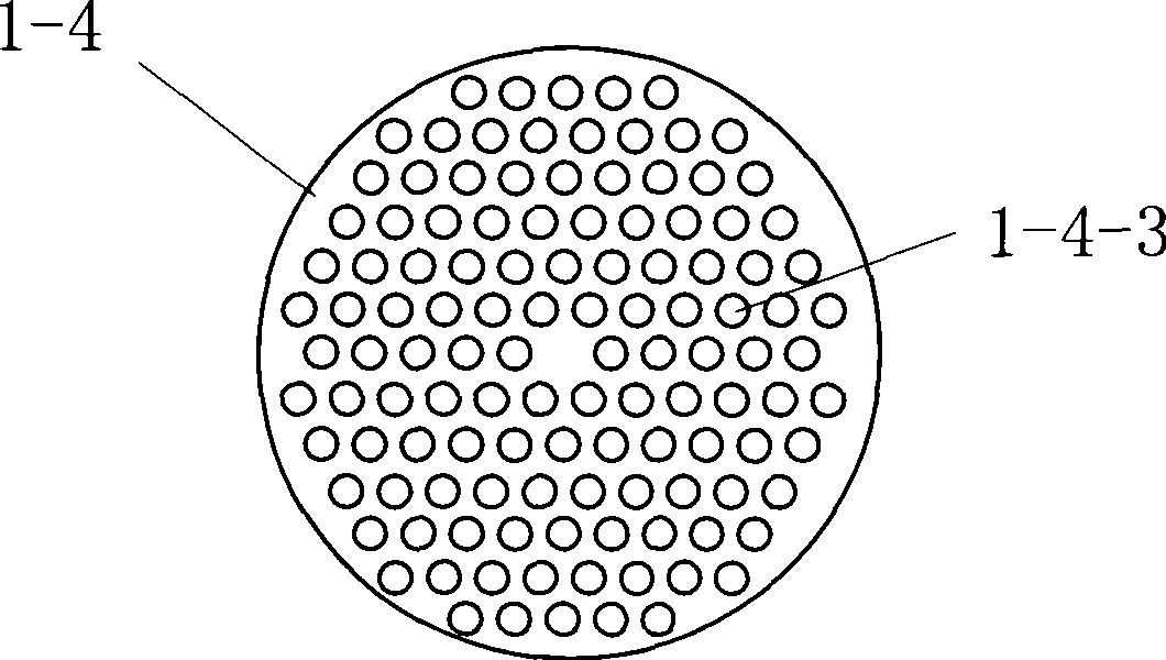
[0080] see Figure 5 This embodiment is basically the same as embodiment 2, except that: the contact cooling spray device 1-3 is also equipped with a liquid level balance pipe 1-3-1, and there are 6 liquid level balance pipes 1-3-1 , The liquid level balance pipe 1-3-1 passes through the corresponding pipe holes 1-4-3 of the upper tube plate 1-4-1 of the tube plate 1-4, and also passes through the corresponding pipe holes 1-4-2 of the lower tube plate 1-4-2 Tube hole 1-4-3. The fixing method is the same as that of the column tubes 1-5 fixed on the tube plate 1-4. The upper port of the liquid level balance pipe 1-3-1 is located from the height of the upper port of each single pipe of the column pipe 1-5 and the water inlet 1-6 of the water inlet 1-6 on each single pipe of the column pipe 1-5 Between -1. After installing the liquid level balance pipe 1-3-1, when the liquid level of the cooling water is higher than the water inlet part 1-6, it can flow into the pipe from the upper po...


PUM

PropertyMeasurementUnit
diameteraaaaaaaaaa

Abstract

The invention discloses a desulfurization and dust removal device for an industrial furnace, the device has a desulfurization dust remover, and the desulfurization dust remover comprises a shell as well as a contact type cooling spray device, a drain pipe, a barrier cap and a water inlet pipe fixed on the shell. The shell is provided with a flue gas inlet, an annular bottom plate and an annular side plate. The contact type cooling spray device is a tube array contact type cooling spray device, and the tube array contact type cooling spray device has a tube array and a tube plate, each single pipe of the tube array penetrates through the corresponding tube hole in the tube plate, and is fixed on the tube plate, each single pipe of the tube array is vertically arranged and is parallel to other pipes, an opening is arranged at the lower end of the body of each single pipe, and a water inlet part is arranged at the upper end head of the pipe body. The invention has advantages that the desulfurization and dust removal efficiency of the device can reach above 98 percent, the equipment investment is less, the running cost and the energy consumption are low, and the device is suitable for large-area promotion and application.

Description

Technical field [0001] The invention belongs to atmospheric environmental protection equipment, and specifically relates to a desulfurization and dust removal device for industrial furnaces and kilns. Background technique [0002] The combustion products of industrial furnaces cause serious pollution to the atmosphere and affect the survival and quality of life of human beings. For example, the sulfur in the fuel of industrial furnaces forms acid rain in the atmosphere, resulting in the reduction of agricultural production, and the harmful micro-dust discharged from industrial furnaces affects humans. Health and pollute the environment. Therefore, all countries in the world have stricter and stricter emission restrictions on various industrial furnaces, and all have established emission standards for industrial furnaces. [0003] Dust removal devices for industrial furnaces and kilns are mainly divided into three categories. One type is dry dust removal devices, which use the gra...

Claims


Application Information

Patent Timeline
Patent Type & Authority Applications(China)
IPC IPC(8): B01D53/78B01D53/18B01D53/50B01D47/00F27B1/18
Inventor 姚立猛
Owner 姚立猛
Why Eureka
Try Eureka