Method of water treatment in steam plant

A water treatment and steam technology, applied in natural water treatment, water treatment parameter control, neutralized water/sewage treatment, etc., can solve the problems of easy to produce scale, difficult to use atomic energy facilities, expensive hydrazine, etc., to prevent scale. attached effect

Inactive Publication Date: 2009-03-25
MITSUBISHI HEAVY IND LTD
View PDF4 Cites 5 Cited by
  • Summary
  • Abstract
  • Description
  • Claims
  • Application Information

AI Technical Summary

Problems solved by technology

Therefore, for example, there are problems in that the differential pressure rises due to protruding or wavy scale deposits on the steam vent hole of the steam generator, and the differential pressure rises due to wavy scale deposits on the flow surface of the orifice and the nozzle part of the flow meter. Adhesion of wavy scale to the inner surface of the thin tube in the feed water heater causes an increase in differential pressure, and adhering of wavy scale to the turbine part of the feed water pump causes an increase in the amount of drive steam or an increase in the current value of the drive motor
[0016] In addition, hydrazine is used in the methods disclosed in the above-mentioned Patent Document 1 and Patent Document 2, but hydrazine is relatively expensive and the impact of hydrazine on the environment is also worthy of attention. Require
[0017] On the other hand, in the methods disclosed in the above-mentioned Patent Document 3 and Patent Document 4, an oxidizing agent is used. However, when the oxidizing agent is injected into the feed water, measures for improving the durability of the secondary system equipment are required separately. Therefore, Its status quo is difficult to apply to nuclear energy facilities
[0018] In addition, in the centrifugal pump used for the water supply pump, since the water in the gap between the surface of the impeller opposite to the surface of the water introduction side and the inner surface of the volute is difficult to flow out to the outside, there will be water stagnation. Scale tends to form on the surface of the impeller in contact with the water stagnant in the gap, and this scale causes a decrease in the efficiency of the centrifugal pump.

Method used


Image

  • Method of water treatment in steam plant
  • Method of water treatment in steam plant
  • Method of water treatment in steam plant

Examples


no. 1 approach

[0037] Hereinafter, the water treatment method of the steam facility according to the first embodiment of the present invention will be described based on FIGS. 1 and 2 .

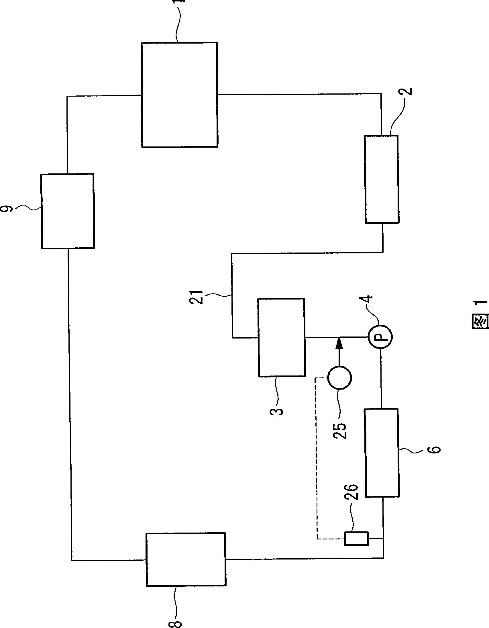
[0038] FIG. 1 is a flowchart showing an example of a steam facility to be treated by a water treatment method according to a first embodiment.

[0039] In the water treatment method of the steam facility of the first embodiment, the steam facility includes: a boiler 8, which generates water vapor by heat from a heat source; a steam turbine 9, which operates by steam from the turbine 8; a condenser 1, It condenses the water vapor discharged from the steam turbine 9 into condensed water; a water supply pump (water supply device) 4, which sends the condensed water condensed by the condenser 1 to the boiler 8; a flow path 21, which is connected to all The boiler 8, the steam turbine 9, the condenser 1 and the water supply pump 4 are circulated. In addition, in this steam facility, a low-pressure heater 2 and a...

no. 2 approach

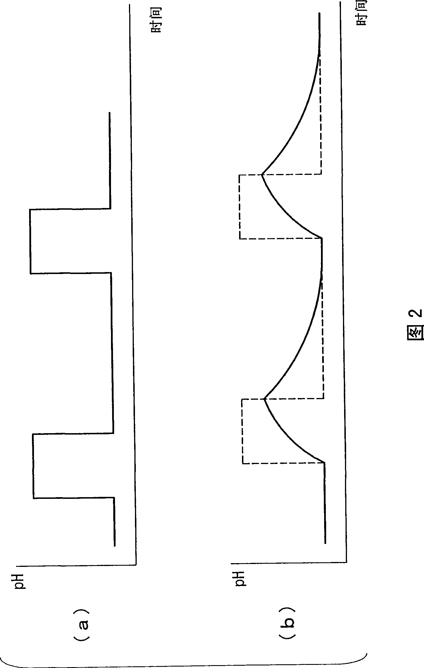
[0056] Hereinafter, a water treatment method of a steam facility according to a second embodiment of the present invention will be described. In addition, since the structure of the steam facility to be the object of the water treatment method of the present embodiment is the same as that of the steam facility to be the object of the water treatment method of the first embodiment shown in FIG. 1 , this embodiment will also be described with reference to FIG. 1 , and omit the description of common structural elements.

[0057] In the water treatment method of a steam facility according to the present embodiment, during operation of the steam facility, substantially periodic chemical environmental fluctuations are given to the flow paths in predetermined equipment provided on the flow paths 21 .

[0058] In the present embodiment, the above-mentioned "predetermined equipment" refers to equipment in which scale adhesion becomes a problem in the steam facility, similarly to the fi...

no. 3 approach

[0071] Hereinafter, a water treatment method of a steam facility according to a third embodiment of the present invention will be described based on FIG. 3 .

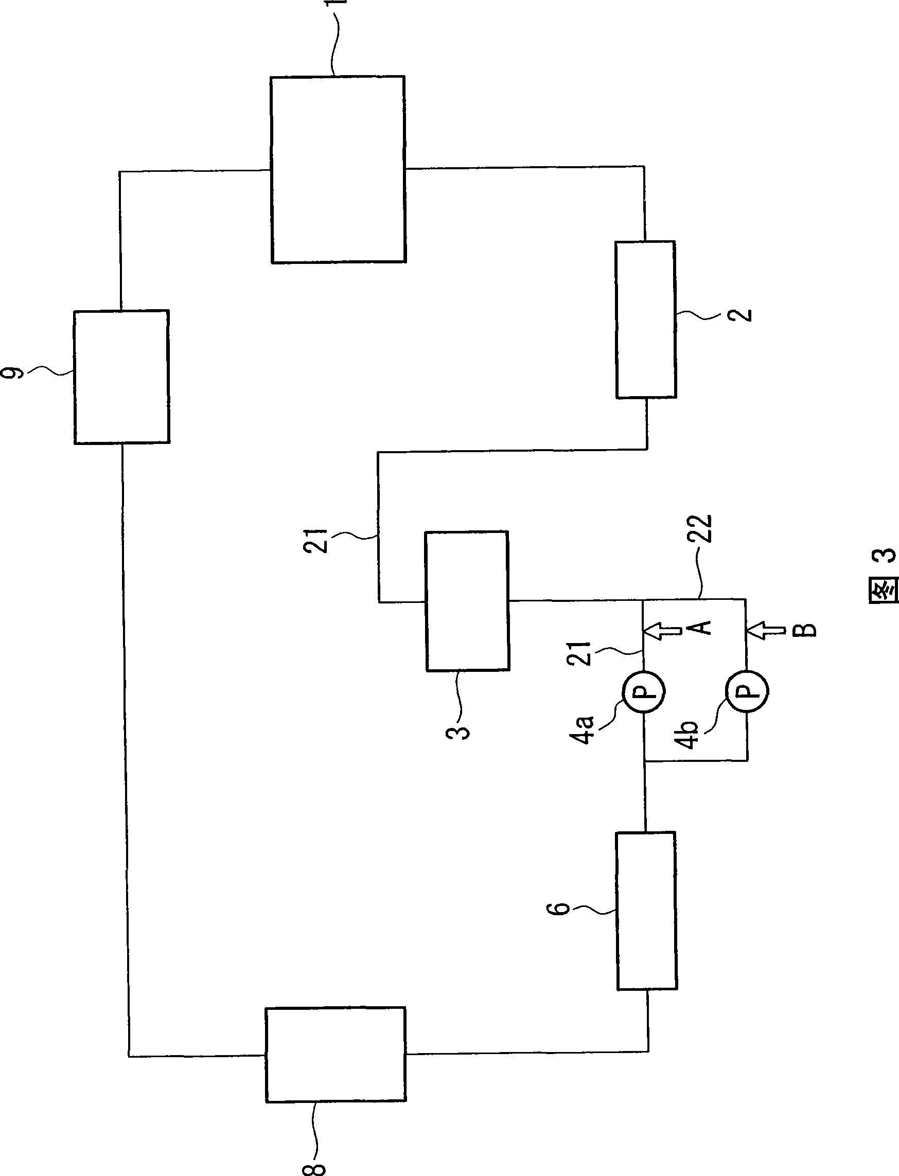
[0072] 3 is a flowchart showing an example of a steam facility to be treated by a water treatment method according to a third embodiment.

[0073]In addition, in the structure of the steam facility to be the object of the water treatment method of this embodiment, except that a plurality of water supply pumps (the first water supply pump 4a and the second water supply pump 4b) are arranged in parallel, the other is the same as that shown in FIG. 1 . Since the steam facilities targeted by the water treatment methods of the first embodiment and the second embodiment are the same, descriptions of common structural elements are omitted.

[0074] In addition, since the types of medicines used in this embodiment are also the same as those in the first and second embodiments, description thereof will be omitted.

[0075] The ...


PUM


Abstract

In a steam plant, the amount of chemicals, such as hydrazine, used is minimized so as to prevent any sticking of scale in specified equipment. During the operation of the steam plant, temporary chemical environmental change or approximately periodic chemical environmental variation is applied to flow channel (21) within given equipment.

Description

technical field [0001] The present invention relates to a water treatment method used in steam facilities such as atomic energy or thermal power generation. In particular, the present invention relates to a method for preventing scale from adhering to water supply pumps, drainage pumps, water supply booster pumps, heaters, orifices, control valves, etc., which are installed on the flow path of the circulation system of a steam facility and where scale adhesion is a problem. Steam facility water treatment methods. Background technique [0002] For example, in a jet boiler of a steam facility for thermal power generation, the cleaner the water quality of the supply water, the more wavy scale tends to be formed on the inner surface of the evaporator tube, and the wavy scale causes an increase in the jet loss of the jet boiler. [0003] As a method for reducing this wavy scale by water treatment, the following methods have been proposed: a method of increasing the concentration...

Claims


Application Information

Patent Timeline
Patent Type & Authority Applications(China)
IPC IPC(8): F22B37/52C02F1/66C02F5/00F01K9/00F22D11/00
CPCC02F2209/44C02F1/008C02F1/66C02F2101/16C02F2209/06C02F2103/023F22B37/48C02F5/00F22B37/56C02F2303/08C02F5/08
Inventor 石原伸夫山内澄男村田和丰金留正人庄田泰彦山上胜彦
Owner MITSUBISHI HEAVY IND LTD
Why Eureka
Try Eureka