Flue gas waste heat recovery method and system for oil and gas boiler

A gas-fired boiler and flue gas waste heat technology, which is applied in the field of flue gas waste heat recovery of oil-fired gas-fired boilers, can solve the problems of large workload, large structure, and difficulty in fully improving heat exchange efficiency, and achieve reduced burden, small size, and favorable The effect of heat and mass exchange

Inactive Publication Date: 2009-04-01
GUANGZHOU DESHANG ENERGY TECH
View PDF1 Cites 23 Cited by
  • Summary
  • Abstract
  • Description
  • Claims
  • Application Information

AI Technical Summary

Problems solved by technology

The atomizing nozzle can make the atomized particles of the fully atomized one-time hot water exchange directly contact with the high-temperature flue gas for heat exchange, fully recover the latent heat of condensation of water vapor in the high-temperature flue gas, and greatly improve the heat exchange efficiency. However, due to the high-temperature f

Method used


Image

  • Flue gas waste heat recovery method and system for oil and gas boiler
  • Flue gas waste heat recovery method and system for oil and gas boiler
  • Flue gas waste heat recovery method and system for oil and gas boiler

Examples


Embodiment 1

[0036] The waste heat recovery method of the fuel gas boiler flue gas of the present invention comprises the following steps:

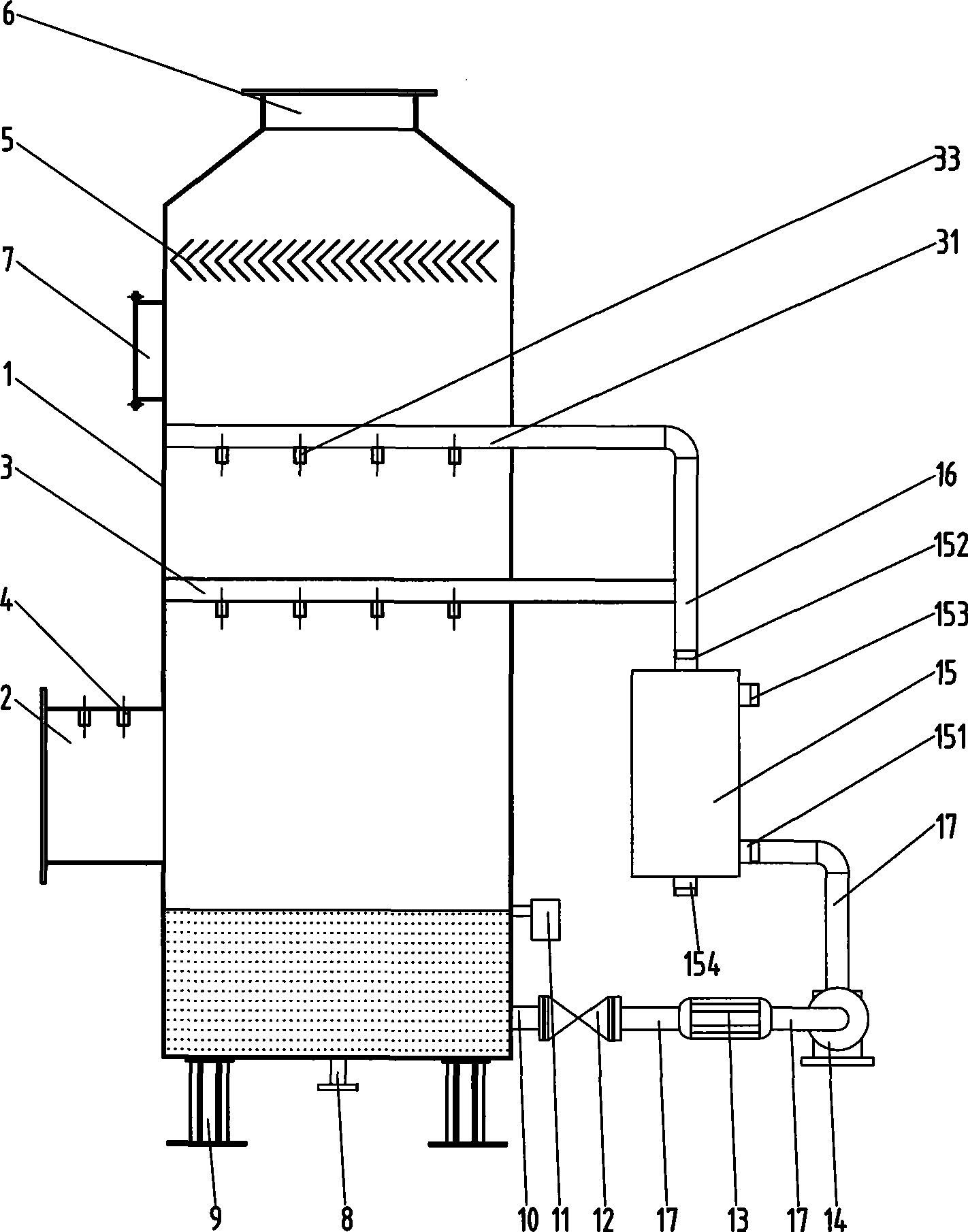
[0037] For the first time, before the high-temperature flue gas enters the main cylinder of the waste heat recovery device, the high-temperature flue gas is pre-sprayed and cooled through nozzles in the high-temperature flue gas inlet socket. Among them, the pre-spray cooling is semi-enveloping spraying of the high-temperature flue gas from top to bottom along the radial direction of the high-temperature flue gas inlet pipe seat in the high-temperature flue gas inlet pipe seat.

[0038] Then, the high-temperature flue gas that has been pre-sprayed and cooled enters the main cylinder along the tangential direction of the main cylinder and flows upward while rotating in the main cylinder. The residence time of the flue gas in the main cylinder can be extended to about 2 seconds, which is more conducive to the heat and mass exchange between the flue gas ...

Embodiment 2

[0050] As another kind of scheme of the present invention, other parts are identical with embodiment 1, and difference is:

[0051] The mass flow rate of high-temperature flue gas in the main cylinder is controlled at 2.0kg / (m 2 s) or so.

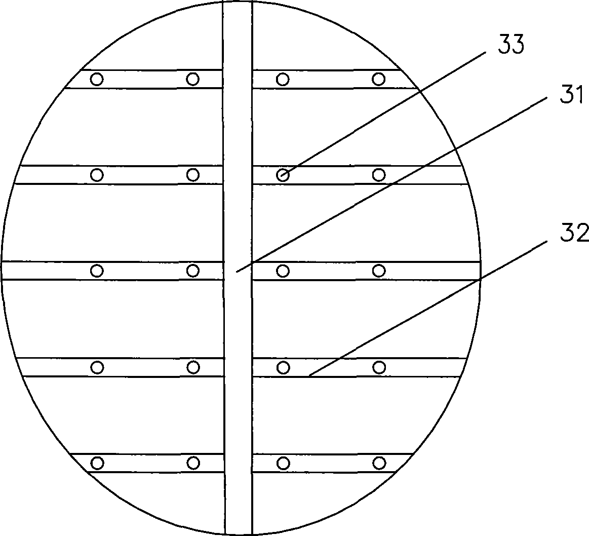
[0052] Three layers of main spraying devices 3 are arranged in the heat exchange space inside the main cylinder 2, and the nozzles of each layer of main spraying devices 3 are staggered from each other, so that the water mist can cover the heat exchange space with the largest area.

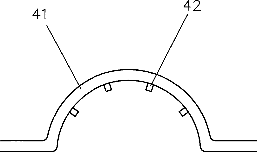
[0053] The pre-spraying device 4 includes three water distribution pipes 41 of the same shape arranged in parallel, the water distribution pipes are arranged on the outer wall of the high-temperature flue gas inlet pipe seat 2, and the opening of the pre-cooling nozzle 42 passes through the through hole provided on the high-temperature flue gas inlet pipe seat 2 Extending to the inside of the high-temperature flue gas inlet pipe seat 2.

Embodiment 3

[0055] As another kind of scheme of the present invention, other parts are identical with embodiment 1, and difference is:

[0056] The mass flow rate of high-temperature flue gas in the main cylinder is controlled at 2.5kg / (m 2 s) or so.

[0057] The distribution main pipe 31, the distribution branch pipe 32 and the atomizing nozzle 33 of the main spraying device 3 are replaced by three shower nozzles distributed in the heat exchange space at intervals. The shower nozzles communicate with the cooling water distribution pipes 16 respectively.

[0058] The mist removal device 5 is a mist eliminator composed of three layers of wire mesh.

[0059] A separate water pump is used to provide cooling water to the pre-spray device 4 .


PUM


Abstract

The invention discloses a recycling method and a system for the afterheat of the smoke gas of oil and natural gas boilers. The method comprises the steps as follows: the smoke gas with high temperature is pre-sprayed and cooled in the inlet pipe seat of the smoke gas with high temperature through a nozzle before entering the main cylinder of an afterheat recycling device; the smoke gas with high temperature after being pre-sprayed and cooled is led to enter into the main cylinder along the tangent direction of the main cylinder, rotate and float upwards in the main cylinder; the smoke gas with high temperature which rises in a rotating way is mainly sprayed and cooled in the middle upper part of the main cylinder through the nozzle; the smoke gas with high temperature flows out of the main cylinder from the upper part of the main cylinder after conversely contacting and changing heat with spraying water fog. In the invention, pre-spraying and cooling are adopted to lead the smoke gas with high temperature to be directly contacted and mixed and change heat with the spraying and cooling water fog when the smoke gas with high temperature passes through a smoke gas inlet; on one hand, the burden of a mist trap can be reduced; on the other hand, the burden of heat and mass exchange of the main cylinder can be reduced, thus leading the volume of the main cylinder to be smaller and the structure of the main cylinder to be more compact.

Description

technical field [0001] The invention relates to a waste heat recovery method and system, in particular to a flue gas waste heat recovery method and system for a fuel-fired gas boiler. Background technique [0002] The flue gas of conventional fuel gas contains a large amount of water vapor. The volume share of water vapor in the flue gas of an oil-fired boiler is about 13%, and that of water vapor in the flue gas of a gas-fired boiler reaches 19%. ℃, or even higher, so the water vapor in the flue gas is discharged with the flue gas in gaseous form, and the latent heat of condensation of the water vapor cannot be effectively utilized, so the heat carried by the water vapor in the flue gas is the main heat loss of the boiler exhaust. part. Taking a certain natural gas as an example, its high calorific value Q gw =39.08MJ / Nm 3 , low calorific value Q dw =35.16MJ / Nm 3 , the difference between the two is 3.92MJ / Nm 3 , that burns 1Nm 3 The water vapor produced by natural ga...

Claims


Application Information

Patent Timeline
IPC IPC(8): F23J15/06
CPCY02E20/30
Inventor 刘武标刘标
Owner GUANGZHOU DESHANG ENERGY TECH
Why Eureka
Try Eureka