Liquid gas gasification method and its circulation type gasification apparatus

A gasification device, liquefied gas technology, applied in the method of container discharge, fixed-capacity gas storage tank, gas/liquid distribution and storage, etc., can solve the problems of insufficient heat absorption area, loss of gasification capacity, condensation, etc., Achieve the effect of high heat exchange efficiency, low manufacturing cost and simple process

Inactive Publication Date: 2009-04-08
陈松平 +1
View PDF0 Cites 6 Cited by
  • Summary
  • Abstract
  • Description
  • Claims
  • Application Information

AI Technical Summary

Problems solved by technology

[0002] At present, the structure of the known electric hot water gasifier is composed of a cylinder with heat preservation, a serpentine pipe, an electric heater, and a gas-liquid phase connection pipe. The liquid liquefied petroleum gas enters the gasifier along the liquid phase pipe inlet, From top to bottom, it flows along the inner serpentine coil immersed in hot water, absorbs the heat transferred by the hot water outside the tube and gasifies, and the gaseous liquefied petroleum gas rises from the middle gas collection pipe, and is supplied after the gas phase tube is regulated. The residual liquid

Method used


Image

  • Liquid gas gasification method and its circulation type gasification apparatus
  • Liquid gas gasification method and its circulation type gasification apparatus
  • Liquid gas gasification method and its circulation type gasification apparatus

Examples


Embodiment Construction

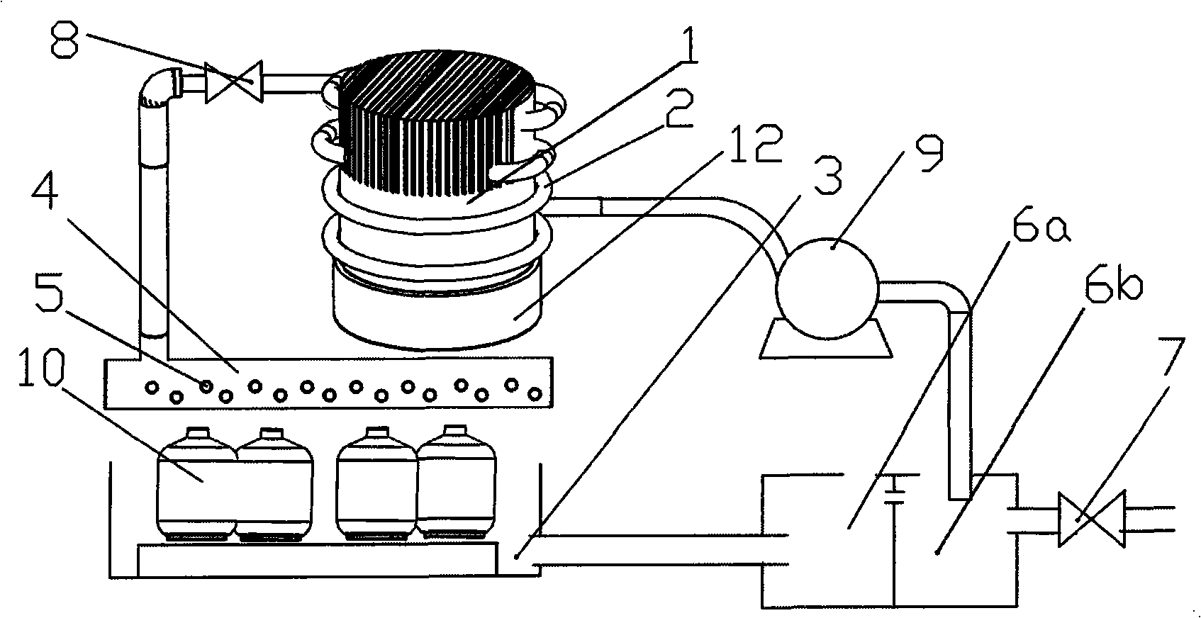
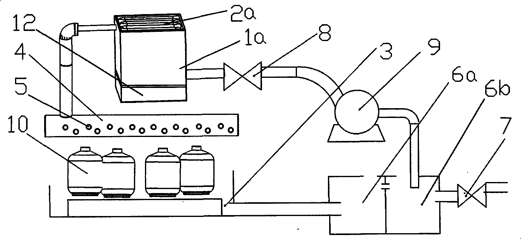
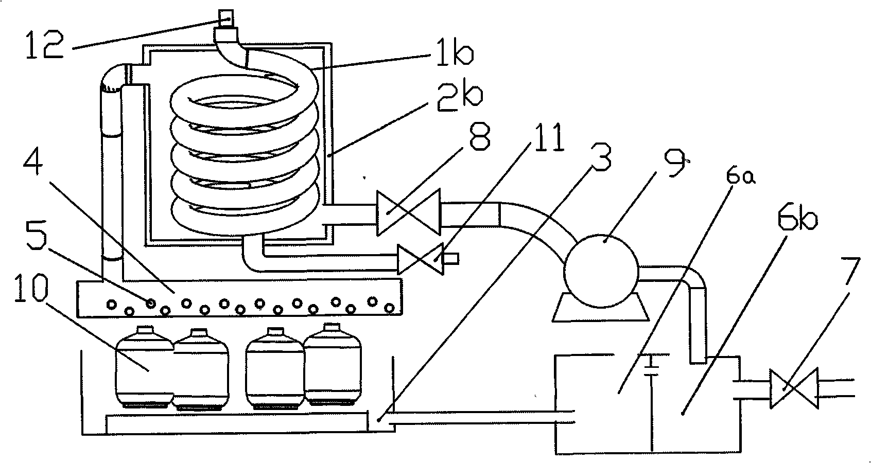
[0016] The present invention will be described in detail in conjunction with the accompanying drawings and embodiments. Such as figure 1 As shown, the lower end of the tube radiator and the fin radiator is connected as one, and the boiler exhaust port 12 is connected with the tube radiator. The part of the heat absorbing coil 2 corresponding to the fin radiator is wound on the fin radiator, and the part corresponding to the tube radiator is wound on the tube radiator. The upper outlet of the heat-absorbing coil 2 is connected to the laterally arranged spray pipe 4 through a valve 8 . A water collection tank 3 is correspondingly provided below the spray pipe 4 , and the air storage tank 10 is placed on the water collection tank 3 corresponding to the water spray hole 5 of the spray pipe 4 . The purification tank is composed of a recovery tank 6a and a water storage tank 6b connected to each other. The water collection tank 3 is connected to the recovery tank 6a. 6b. The rep...


PUM


Abstract

The invention discloses a liquid gas gasifying method and a circular type gasifying device thereof. The method has simple process as well as energy saving and environment protection. The gasifying device has simple structure and is energy-saving and environment-friendly. The gasifying method comprises the following steps: the hot waste gas at the discharge outlet of a boiler is used for heating water through a heat exchanger, the heated water is sprayed on a gas holder and gasifies the liquid gas through heating, after that, the water is recovered and delivered to the heat exchanger through a water supply device for second heat exchange with the hot waste gas. The gasifying device comprises a heating appliance consisting of a sheet heating body and a tube type heating body, the heat exchanger arranged on the heating appliance and consisting of a heat absorption pipe coil, a spraying device connected with the outlet of the heat absorption pipe coil, a catchwater channel arranged relative to the spraying device and connected with a purifying tank, and a water pump connected between the inlet of the heat absorption pipe coil and the purifying tank.

Description

Technical field: [0001] The invention relates to a liquefied gas gasification method and a circulating gasification device thereof. Background technique: [0002] At present, the structure of the known electric hot water gasifier is composed of a cylinder with heat preservation, a serpentine pipe, an electric heater, and a gas-liquid phase connection pipe. The liquid liquefied petroleum gas enters the gasifier along the liquid phase pipe inlet, From top to bottom, it flows along the inner serpentine coil immersed in hot water, absorbs the heat transferred by the hot water outside the tube and gasifies, and the gaseous liquefied petroleum gas rises from the middle gas collection pipe, and is supplied after the gas phase tube is regulated. The residual liquid of liquefied petroleum gas is discharged through the sewage pipe at the bottom of the gas collection pipe. However, this kind of gasifier has a complex process structure, insufficient heat absorption area, and low gasific...

Claims


Application Information

Patent Timeline
IPC IPC(8): F17C7/04F17C9/04
Inventor 陈松平黄浏娜
Owner 陈松平
Why Eureka
Try Eureka