Method and apparatus for forming porous metal implants

A technology of porous metals and implants, applied in metal processing equipment, joint implants, joint implants, etc., can solve the problems of implant corrosion and service life reduction

Inactive Publication Date: 2009-04-08
BIOMET MFG CORP
View PDF2 Cites 44 Cited by
  • Summary
  • Abstract
  • Description
  • Claims
  • Application Information

AI Technical Summary

Problems solved by technology

Many of these methods use different metals to form the base and porous layer, leading to corrosion and reduced lifespan of the implant

Method used


Image

  • Method and apparatus for forming porous metal implants
  • Method and apparatus for forming porous metal implants
  • Method and apparatus for forming porous metal implants

Examples


Embodiment Construction

[0023] The following description is of an illustrative nature only and is not intended to limit the invention, its application or uses in any way. Although various embodiments have been described in connection with porous metal implants for use with knee or hip prosthetic devices, it is to be understood that the implants and methods of the present invention may have any suitable substrate or shape and may be used in Any suitable program can be used, not just those exemplified.

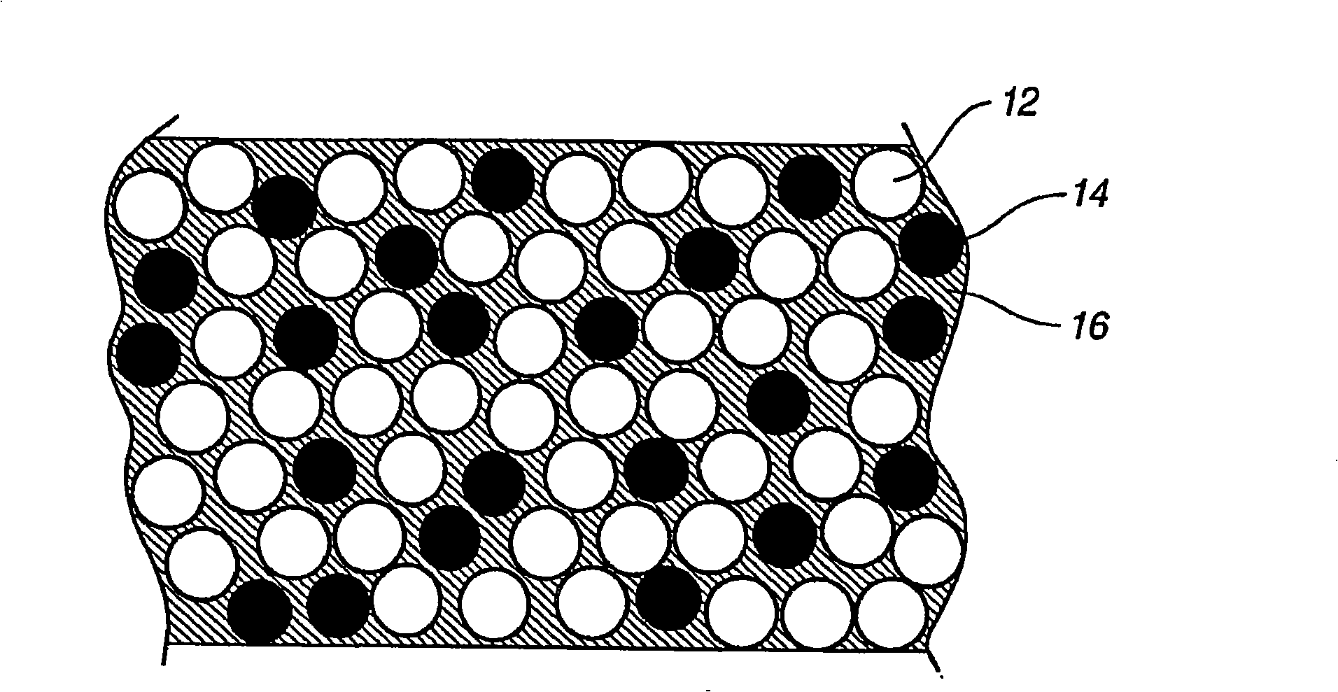
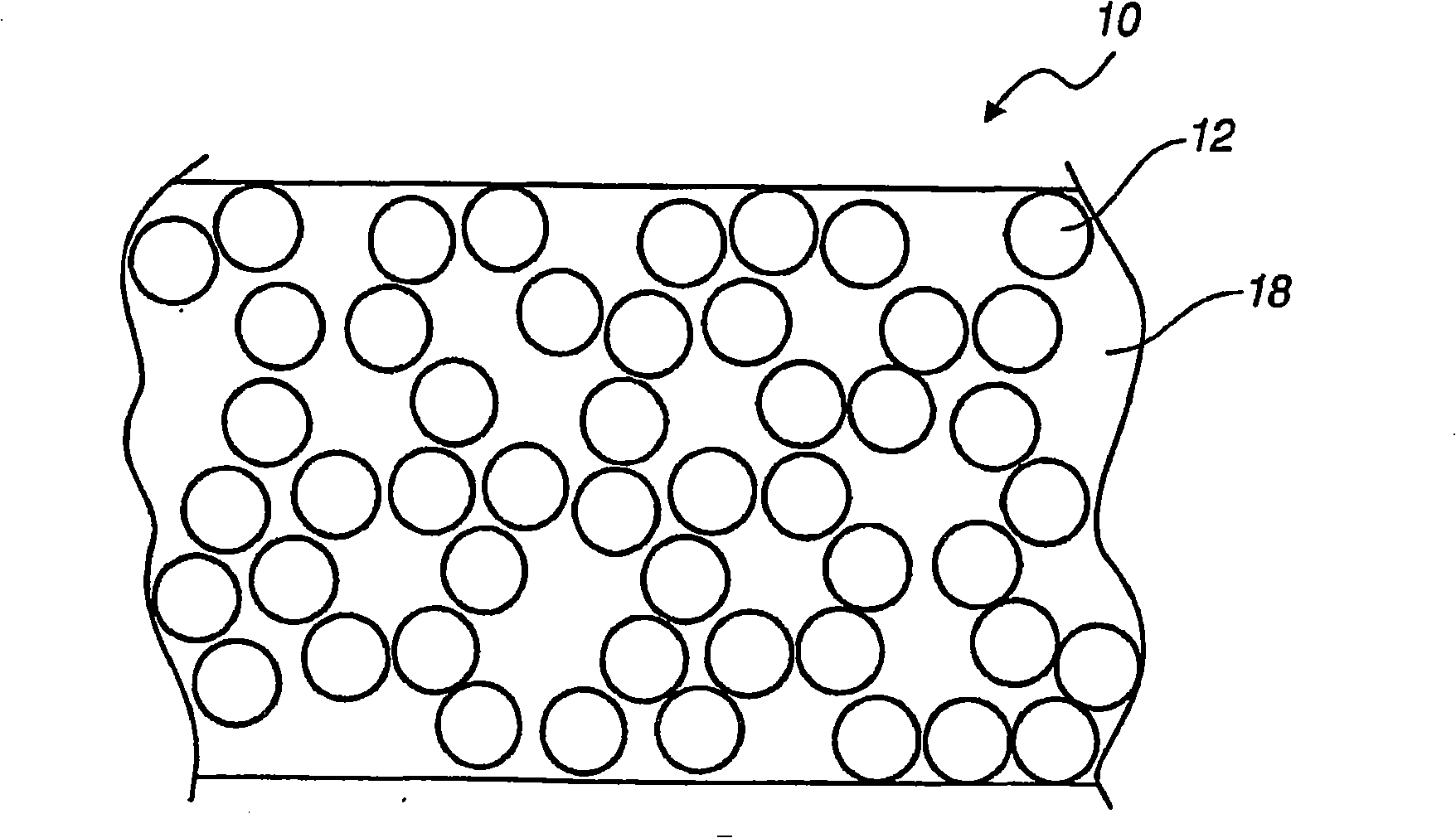
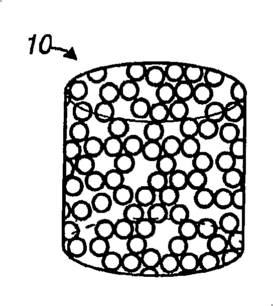
[0024] refer to figure 1 and figure 2 , the porous metal implant 10 may be formed from a mixture of metal powder 12 , pore former 14 and non-polar liquid binder 16 . Porous metal implant 10 is formed by heating the mixture to a temperature sufficient to remove pore forming agent 14 and non-polar liquid binder 16 to leave a plurality of pores 18 between interconnected powder 12 particles.

[0025] Metal powder 12 may be any metal or alloy suitable for use as an implant and providing the desired stre...


PUM

PropertyMeasurementUnit
particle diameteraaaaaaaaaa
thicknessaaaaaaaaaa

Abstract

The present invention relates to a method for providing a porous metal implant. A mixture of a biocompatible metal, a spacing agent, and a binder is provided. The mixture is formed into a shaped the spacing agent is removed to form a plurality of pores in the implant. A shaped porous metal implant is also provided.

Description

[0001] related application [0002] This application is related to U.S. Patent Application 11 / 357,868 (Attorney Docket No. 5490-000410 / CPB), entitled "Methods and Apparatus for Porous Implants," the disclosure of which is incorporated herein by reference, filed herewith "Methods and Apparatus for Porous Implants," and jointly assigned to Biomet Manufacturing Corp. of Warsaw, Indiana. technical field [0003] The present invention relates to porous metal implants and methods for their manufacture. Background technique [0004] Porous metal implants are used to promote the growth of surrounding bone and soft tissue into the implant. When the metal has sufficient porosity, integrity, and continuity, the porous implant acts as a scaffold for tissue ingrowth to provide the desired load-bearing strength to the implant site. [0005] Porous implants can be formed by removing small pieces from the metal substrate, for example by etching a solid piece of metal. Implants can also b...

Claims


Application Information

Patent Timeline
Patent Type & Authority Applications(China)
IPC IPC(8): A61L33/00B22F1/103
CPCA61F2002/30878A61F2002/30011A61L2300/428A61F2002/30383A61F2002/30169A61F2002/30604A61F2230/0069A61L27/56A61F2002/30451A61F2310/00131A61L2300/406A61F2310/00059B22F2998/10A61F2002/30736A61F2002/30224A61F2002/30064A61F2002/3092A61F2310/00029A61L2300/414A61F2/34C09C1/00A61F2310/00592A61F2002/30166A61F2230/0065A61F2002/30968A61F2002/3411A61F2002/30261A61F2310/00023A61F2/30767A61F2002/30235A61F2310/0097A61F2002/30827A61F2230/0082A61F2/38A61F2220/0025A61F2/389A61L27/04A61F2310/00958B22F3/1125A61F2250/0023A61F2230/0067B22F2001/0066A61F2220/0058A61F2230/0028A61F2310/00976A61L2300/25A61F2230/0047A61L27/54A61F2002/302A61F2310/00017A61L2300/64A61F2002/30454A61F2/30907A61F2/3859A61F2002/30205A61L2300/606A61F2002/305B22F1/103B22F1/10B22F3/04B22F3/02B22F3/1021B22F3/1216C01P2004/61A61K35/12
Inventor 内德·M·哈曼詹姆斯·B·弗莱明伊丽莎白·A·施吕特艾萨克·詹森杰森·D·梅里德穆克什·库马尔
Owner BIOMET MFG CORP
Why Eureka
Try Eureka