High precision high rigidity closed type fluid static pressure / dynamic-static pressure rotary table

A technology of rotary table and hydrostatic pressure, applied in the direction of manufacturing tools, metal processing equipment, metal processing machinery parts, etc., can solve the problems of low rigidity, limited bearing rigidity, melting of bearing pairs, etc., to reduce volume and weight, load bearing Effects of increased capacity and increased radial rigidity

Active Publication Date: 2009-04-15
BEIJING PROSPER PRECISION MACHINE TOOL CO LTD
View PDF0 Cites 36 Cited by
  • Summary
  • Abstract
  • Description
  • Claims
  • Application Information

AI Technical Summary

Problems solved by technology

[0005] For a single axial and radial hydrostatic / dynamic and static pressure bearing or a single closed static pressure / dynamic and static pressure bearing in the axial direction, it can be known from the principle of static pressure / dynamic and static pressure that when the load changes, the clearance changes, The pressure feedback capability and response speed of the unilateral pressure chamber are very limited, which determines the limited stiffness of the bearing; when the load is too large, it will even cause dry friction of the bearing pair and cause instantaneous high temperature, resulting in melting and burning of the bearing pair. necrosis
Therefore, like the aforementioned open hydrostatic / dynamic and static pressure structure, the rigidity is low; it cannot be used for strong cutting and grinding, and it cannot meet the requirements of high precision, high rigidity, and heavy load required by industrial production, making the entire equipment loss. efficient production capacity

Method used


Image

  • High precision high rigidity closed type fluid static pressure / dynamic-static pressure rotary table
  • High precision high rigidity closed type fluid static pressure / dynamic-static pressure rotary table

Examples


Embodiment Construction

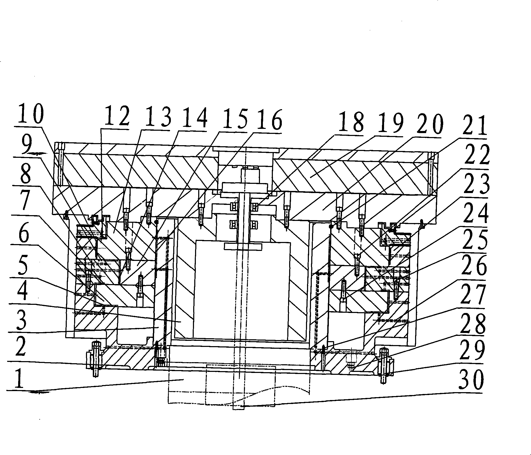
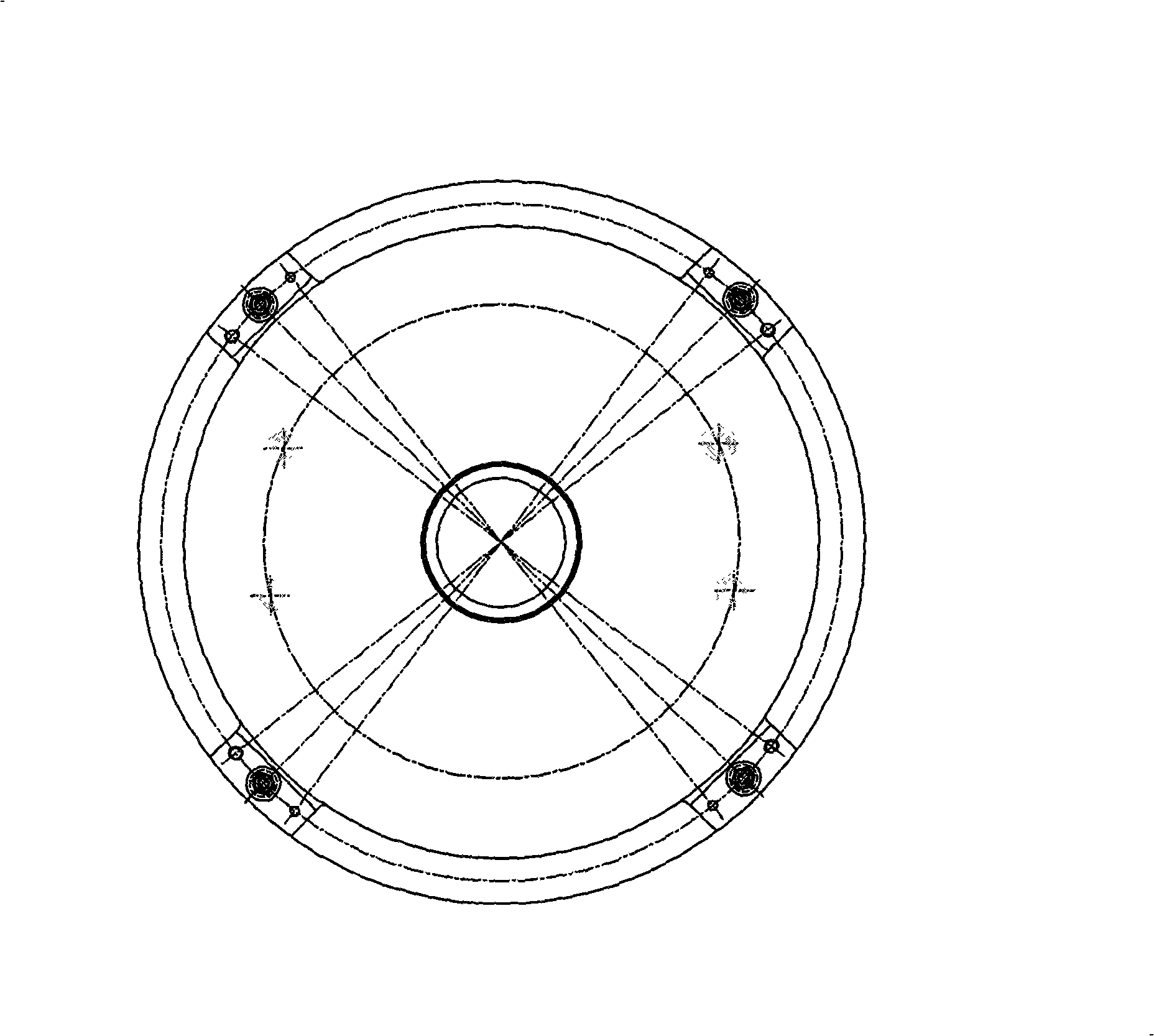
[0015] see figure 1 as shown, figure 1 It is the most preferred embodiment of the present invention, a high-precision and high-rigidity closed hydrostatic / dynamic and static rotary table, including: a turntable driving part 1, an outer base 2, radial static / dynamic and static pressure guide rails 3, 8 and 23, a drive Connecting shaft 4, axial bearing static pressure / dynamic and static pressure bearings 5 ​​and 9, axial balance bearings 7 and 12, slewing rings 6 and 13 and 15, radial static pressure / dynamic and static pressure bearings 10 and 14 and 16, cable support bearings 18. Electromagnetic chuck or other card body 19. Workbench 20, sealing ring 21, connecting screws and positioning pins 22 and 24 and 25 and 27, static pressure / dynamic and static pressure fluid inlet 26, fluid outlet 28, adjustable lock for the workbench Tight pair 29, cable 30.

[0016] The drive part 1 of the rotary table can be directly connected to the motor, or can be connected to the drive coupling...


PUM


Abstract

The invention provides a closed fluid static pressure/ dynamic static pressure revolving worktable with high precision and rigidity, and relates to the field of automatic equipment of precision machinery. A plurality of axial bearings and radial bearings arranged along the axial direction are fixed by a plurality of slewing rings and bearing guide rails; the revolving worktable is provided with a balanced bearing to balance; kinematic pairs of a plurality of bearings rotate synchronously and are connected; fixed pairs of the bearings are connected through a base of the worktable; and sliding pairs of the radial bearings and bearing pairs of the axial bearings move rigidly, integrally and synchronously; and a relatively still sliding surface of the sliding pair of each bearing is provided with an oil chamber. Under the conditions that fluid pressure of the revolving worktable is same and the volume is equal, the axial rigidity, the radial rigidity and the bearing capacity are multiply improved, and the improved multiple is in direct proportion to the number of the bearings. The revolving worktable has the advantages of convenient design, simple manufacture, low cost, high precision and no abrasion. The revolving worktable is a key part of a high-precision metal working machinery, in particular to a functional part of large and oversize heavy equipment by using the key technology, and has more remarkable advantages in manufacturing equipment in the fields of navigation, astronavigation, large aircraft, and the like.

Description

technical field [0001] The invention relates to a high-precision, high-rigidity, heavy-duty rotary table for automatic mechanical equipment, in particular to a rotary table that is required to be carried by a precision machine tool or other automatic mechanical equipment. Background technique [0002] The rotary table technology related to this application is used for small and medium-sized precision metal cutting machine tools and high-precision, high-rigidity, heavy-duty large-scale technical equipment required in the manufacture of navigation, aerospace, large aircraft, and large-scale power generation equipment, and other large-scale technical equipment that utilizes rotary table The mechanical automation equipment carried, especially precision parent machines such as high-precision vertical lathes, vertical grinders, counter grinders, horizontal boring and milling machines, and technical equipment directly applied to extra-large, high-rigidity, high-precision, heavy-duty...

Claims


Application Information

Patent Timeline
Patent Type & Authority Applications(China)
IPC IPC(8): B23Q1/25B23Q1/38
CPCF16C32/0696F16C2322/39
Inventor 吴行飞吕桂芳杨文英
Owner BEIJING PROSPER PRECISION MACHINE TOOL CO LTD
Why Eureka
Try Eureka