Loop filter circuit for charge pump phase-locked loop

A technology of loop filter circuit and filter circuit, which is applied in the field of phase-locked loop, can solve problems such as reference spurs, and achieve the effect of improving performance

Inactive Publication Date: 2009-04-15
BEIJING RFMC TECH CORP
View PDF0 Cites 24 Cited by
  • Summary
  • Abstract
  • Description
  • Claims
  • Application Information

AI Technical Summary

Problems solved by technology

[0010] The purpose of the present invention is to solve the reference spurious problem caused by the mismatch of the upper and lower branch current sources in the charge pump, and provide a loop filter circuit for the charge pump phase-locked loop

Method used


Image

  • Loop filter circuit for charge pump phase-locked loop
  • Loop filter circuit for charge pump phase-locked loop
  • Loop filter circuit for charge pump phase-locked loop

Examples


Embodiment Construction

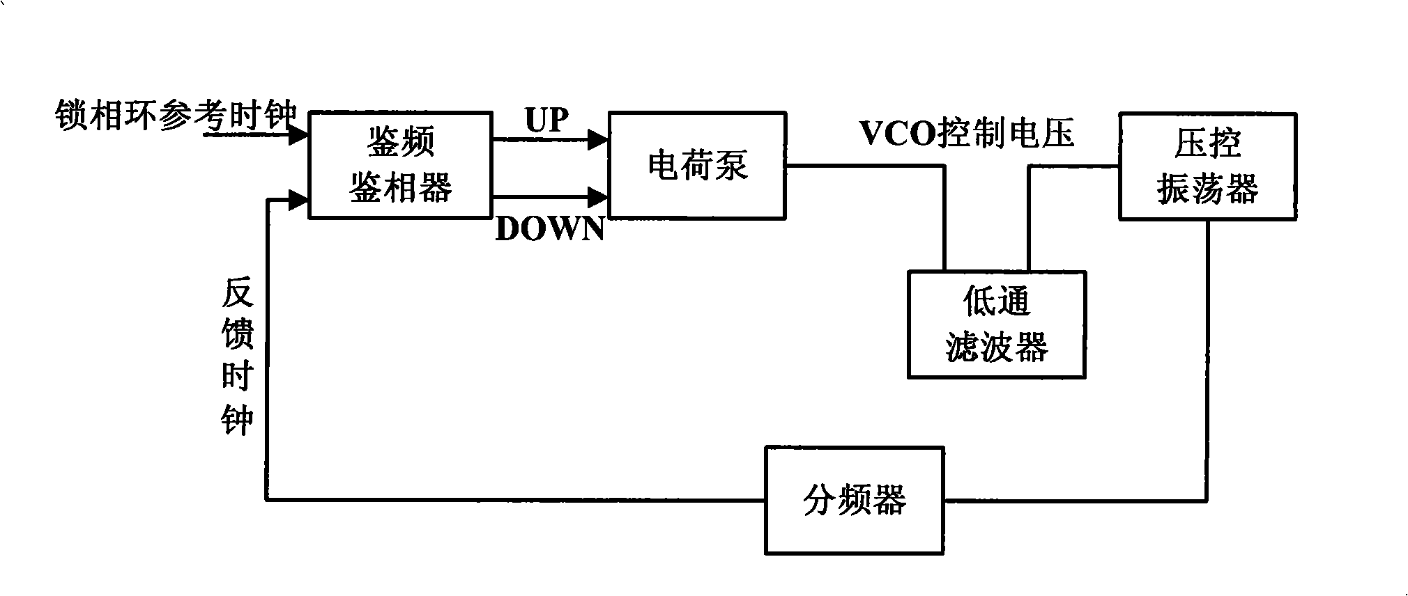
[0042] Such as Figure 7 As shown, in one embodiment of the present invention, the charge pump phase-locked loop includes a frequency detector, a charge pump, a loop filter circuit, a frequency divider and a voltage-controlled oscillator, wherein the front end of the loop filter circuit is connected to A charge pump is connected to a voltage-controlled oscillator at the rear. The loop filter circuit includes a front-end buffer circuit composed of a capacitor C2_1, a delay switch S1 and a back-end filter circuit. The back-end filter circuit includes three parallel branches, wherein the third branch is composed of capacitor C2_2, the second branch is composed of resistor R1 and capacitor C1 connected in series, and the third branch is composed of resistor R2 and capacitor C3 connected in series. The delay switch S1 is arranged between the front-end buffer circuit and the back-end filter circuit, the delay switch S1 can delay the reference clock signal of the frequency and phase...


PUM


Abstract

The invention provides a loop filter circuit used in a charge pump phase-locked loop. The charge pump phase-locked loop comprises a frequency and phase discriminator, a charge pump, a loop filter, a frequency divider and a voltage-controlled oscillator; the front end of the loop filter is connected with the charge pump and the rear end is connected with the voltage-controlled oscillator; the loop filter circuit comprises a control logic, a front buffer circuit, a time delay switch and a rear filter circuit; when the time delay switch is conducted, the whole loop filter circuit can operate normally; but when the time delay switch is off, the charge pump is conducted with the front buffer circuit and is not conducted with the rear filter circuit; the time delay circuit of the time delay switch refers delays time of the clock, and the on-off of the time delay switch is controlled by the control logic of the loop filter circuit; by adopting the circuit, the problem of stray reference caused by the mismatching of the upper and lower branch currents in the charge pump is solved, and the performance of the loop filter circuit of the charge pump phase-locked loop is improved.

Description

technical field [0001] The invention relates to the field of phase-locked loops, in particular to a loop filter circuit for a charge pump phase-locked loop. Background technique [0002] Phase-locked loops are widely used in communication transceivers. In high-speed wired communications, phase-locked loops are used for clock recovery and clock generation. In wireless communication, phase-locked loop is used to generate local oscillation, modulation and demodulation. Since almost all integrated phase-locked loops adopt the charge pump phase-locked loop structure at present, the following analysis is mainly based on the charge-pump phase-locked loop circuit. [0003] figure 1 Shown is a block diagram of the structure of a typical charge pump phase-locked loop. The PLL consists of a phase detector, a charge pump, a loop filter circuit, a frequency divider and a voltage-controlled oscillator (VCO). The loop filter circuit usually adopts a low-pass filter. The entire loop c...

Claims


Application Information

Patent Timeline
Patent Type & Authority Applications(China)
IPC IPC(8): H03L7/08H03L7/093H03K17/28
Inventor 陈永聪马槐楠杨沛锋王文申
Owner BEIJING RFMC TECH CORP
Why Eureka
Try Eureka