
Double-inclined transducer

A transducer and chip technology, applied in the field of ultrasonic probes, can solve the problems of poor signal-to-noise ratio, poor contact reliability, low sensitivity, etc., and achieve the effects of small change in K value, improved reliability, and strong signal-to-noise ratio

Inactive Publication Date: 2009-04-22
周南岐
View PDF0 Cites 8 Cited by
  • Summary
  • Abstract
  • Description
  • Claims
  • Application Information

AI Technical Summary

Problems solved by technology

[0002] At present, in the chemical industry and nuclear power industry, the quality requirements for various workpieces are very high, and each workpiece needs to be inspected. The existing technology has X-ray inspection, which pollutes the environment very much and is very inconvenient. Ultrasound is used to detect defects, so the requirements for it are getting higher and higher
In the use of workpieces, the use of stainless steel workpieces is very large, especially stainless steel is divided into fertenite, martensite, austenite, nickel-based alloys, and the processing of materials is divided into forging, wrench, centrifugal Casting, manual welding, automatic welding, etc. form various materials with different sound velocities and interface reflections, mainly resulting in scattering, crystal interface scattering and diffraction, etc. To solve the defects in the detection materials, mostly shear wave single crystal or double crystal is used, and its sensitivity is low. , The signal-to-noise ratio is poor, and it is difficult to identify defects. Especially when testing thick parts, the flaw detection of the welded part is more difficult. The depth of the flaw detection is not enough, resulting in incomplete flaw detection. In addition, the contact method is used for detection. The contact surface of the workpiece will be worn, which will affect the property value of the probe. At the same time, the reliability of the contact is poor, and it is easy to cause false alarms and losses during the flaw detection process.

Method used


Image

  • Double-inclined transducer
  • Double-inclined transducer
  • Double-inclined transducer

Examples


Embodiment Construction

[0016] The present invention will now be described in further detail in conjunction with the accompanying drawings and preferred embodiments. These drawings are all simplified schematic diagrams, which only illustrate the basic structure of the present invention in a schematic manner, so they only show the configurations related to the present invention.

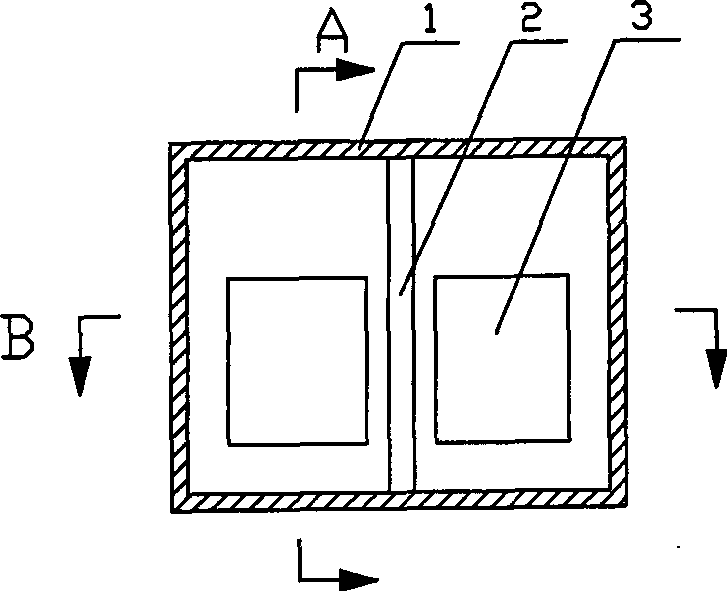
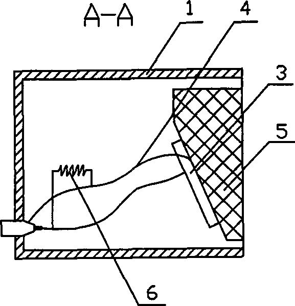
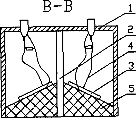
[0017] Such as figure 1 , figure 2 , image 3 The bislant transducer shown has a hollow shell 1 with one end open, a wedge 5 is arranged at the open end of the shell 1, and at least two wafers 3 are arranged in the shell 1, and the front and back of the wafer 3 are connected with wires 4 and wires respectively. 4 connected to the socket, the two chips 3 are composed of a transmitting chip and a receiving chip, the transmitting chip, the receiving chip and the opening end face of the shell 1 form an incident angle, the transmitting chip and the receiving chip have a deflection angle, and there is a gap between the transmit...


PUM


Abstract

The invention relates to a diclinic transducer which is used for detecting the defects of a workpiece, belonging to the technical field of ultrasonic probe. The diclinic transducer is provided with a hollow shell with an opening at one end; the opening end of the shell is provided with a wedge block; the shell is internally provided with at least two wafers; the positive surface and the reverse surface of the wafer are respectively connected with a leading wire which is connected with a socket; the two wafers consist of an emitting wafer and a receiving wafer; the emitting wafer and the receiving wafer have an incident angle of 33-70 degrees with the opening end surface of the shell, and the emitting wafer has a deviation angle of 0.3-8 degrees with the receiving wafer; a sound boarding is arranged between the emitting wafer and the receiving wafer; the ultrasonic frequency emitted by the emitting wafer is within 1MHz to 4MHz; the wafer surface is provided with noise elimination material; the area of the wafer is within 6mm*10mm to 15mm*30mm, the flaw detection depth is large and the detection exactness is high.

Description

technical field [0001] The invention relates to the field of ultrasonic probes, in particular to a double-slope transducer that can easily detect workpiece defects. Background technique [0002] At present, in the chemical industry and nuclear power industry, the quality requirements for various workpieces are very high, and each workpiece needs to be inspected. The existing technology has X-ray inspection, which pollutes the environment very much and is very inconvenient. Ultrasound is used to detect defects, so the requirements for it are getting higher and higher. In the use of workpieces, the use of stainless steel workpieces is very large, especially stainless steel is divided into fertenite, martensite, austenite, nickel-based alloys, and the processing of materials is divided into forging, wrench, centrifugal Casting, manual welding, automatic welding, etc. form various materials with different sound velocities and interface reflections, mainly resulting in scatterin...

Claims


Application Information

Patent Timeline
Patent Type & Authority Applications(China)
IPC IPC(8): G01N29/24G01N29/04
Inventor 周南岐
Owner 周南岐
Learn More