
Method and device for improving flow character of gas liquid bubble column with row tubes

A technology of flow characteristics and bubble towers, applied in chemical methods, chemical instruments and methods, chemical/physical processes, etc. for reacting liquid and gaseous media, and can solve the difficulty of enlarging the ratio of empty towers in reactors with heat exchange tubes , no flow measurement data support, serious gas-liquid backmixing, etc., to reduce the difficulty of amplification, improve reaction performance, and reduce the effect of gas-liquid backmixing

Inactive Publication Date: 2011-01-12
ZHEJIANG UNIV
View PDF2 Cites 6 Cited by
  • Summary
  • Abstract
  • Description
  • Claims
  • Application Information

AI Technical Summary

Problems solved by technology

Patent [9] proposes to set up multiple vertical jacketed cylinders in the tower, the air bubbles and slurry flow inside and outside the cylinders, and the cooling medium flows through the jackets. It is believed that this arrangement can improve fluid backmixing and improve reactor performance , however, none of the above measures are directly supported by flow measurement data
[0005] Recently, the inventors used special experimental techniques to measure the velocity distribution and gas holdup distribution in the bubble column installed with vertical tube bundles in detail, and found that after the vertical tube bundles were added, the flow velocity distribution and gas holdup distribution would not It tends to be flat, but it will make it steeper (see Comparative Example 1), which makes the gas-liquid backmixing more serious, and the reactor with heat exchange tubes is more difficult to scale up than the empty tower

Method used


Image

  • Method and device for improving flow character of gas liquid bubble column with row tubes
  • Method and device for improving flow character of gas liquid bubble column with row tubes
  • Method and device for improving flow character of gas liquid bubble column with row tubes

Examples


Embodiment 1

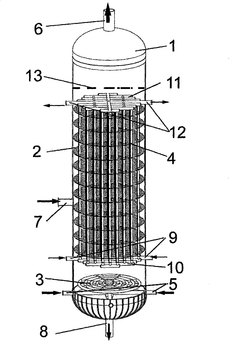
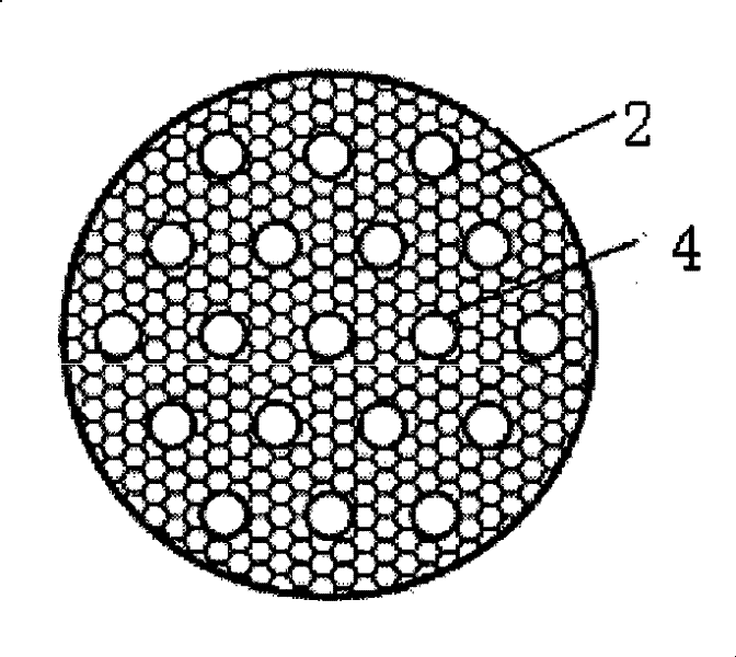
[0037] Slurry bed cold model experimental device, with a diameter of 500mm and a liquid level height of 4000mm, with a perforated plate gas distributor installed at the bottom. A number of galvanized iron vertical heat exchange tubes with a length of 4000mm and a diameter of 25mm are evenly arranged from the top of the gas distributor to the liquid level. The fully developed flow zone in the middle section of the tower is evenly arranged with 10 floors, such as figure 2 The grid-type damping member shown has a rhombus-shaped mesh, and each layer of damping net is evenly arranged on the entire cross-section of the tower, and the vertical heat exchange tube bundles vertically pass through the 10-layer grid-type damping member. The specific structural parameters of tube bundles and damping grids are listed in Table 1, where the damping area density A R (m 2 / m 3 ) is the total cross-sectional area of ​​the latitude and longitude of the multi-layer grid / the slurry volume surro...

Embodiment 2

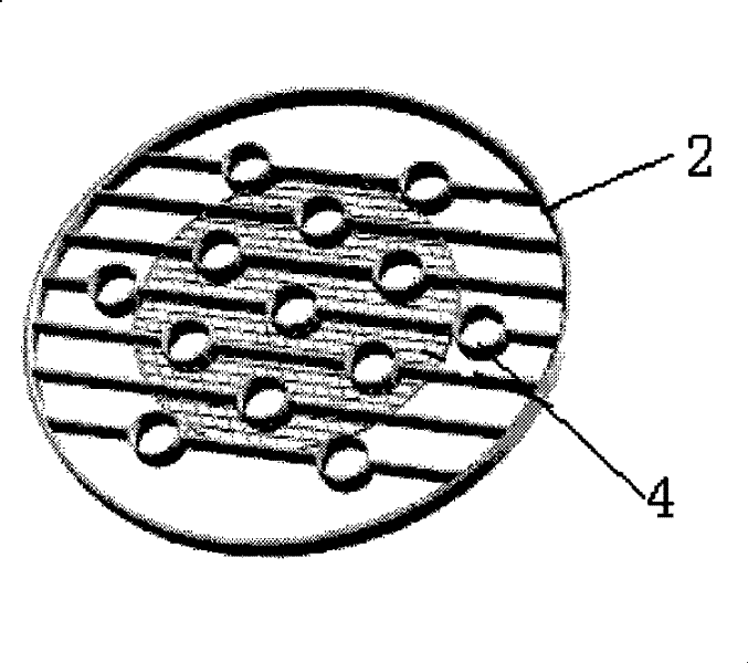
[0064] In addition to the damping area density, the radial distribution of the damping area density is also an important parameter to characterize the performance of the grid-type damping internal member. In order to investigate the influence of different damping area density distributions on the flow velocity, this example compares two grid distributions: one is to arrange the damping grid evenly on the entire tower cross section, and the other is to arrange the damping grid only in the central area of ​​the tower mesh, with no damped mesh in the peripheral region. Still using the same dense array of tubes as in Example 1 (the number of tubes N=40), and the small hole grid with the same parameters and number of layers (the parameters of the tubes and grids are listed in the last row of Table 1). Different from Embodiment 1, the diameter of each layer grid in this example is only half of the tower diameter (250mm), and it is arranged in the central area of ​​the tower. In the...


PUM


Abstract

The invention discloses a method and a device used for improving the flowing characteristic of the slurry bubble tower with row tubes; the device comprises a tower body, a gas distributor and a vertical heat exchanging row tube bundle; the lower end of the vertical heat exchanging tube bundle is connected with a liquid distributor which is fixed at the lower part of the tower body and the upper end thereof is connected with a liquid collector which is fixed at the upper part of the tower body; a plurality of layers of horizontal grid-typed damp internal components are arranged between the liquid distributor and the liquid collector; the heat exchanging row tube bundle vertically passes through the horizontal grid-typed damp internal components; each layer of the grids is fixed on the tower wall and the row tubes; and by arranging the horizontal grid-typed damp internal components in the slurry bubble tower which is provided with vertical row tube bundles; and the horizontal damp internal components block the flowing of the slurry and air bubbles in the tower, inhibit the flowing craggedness effect caused by the row tube bundle, and reduce the returned mixing of the fluid, thus improving the flowing characteristic of the slurry reactor.

Description

technical field [0001] The invention relates to a method and a device for improving the flow characteristics of a slurry bubble column with heat exchange tubes. Background technique [0002] Gas-liquid bubble tower or gas-liquid-solid three-phase bubble reactor (also known as slurry bed bubble tower) is a reaction device widely used in many fields such as chemical industry, energy, environment, biochemistry, etc. It is used for gas-liquid Two-phase or gas-liquid-solid three-phase mass transfer and reaction operations, such as Fischer-Tropsch synthesis, hydroliquefaction, carbonylation, oxidation, halogenation, fermentation, gas absorption and other processes. There are two main difficulties encountered in the design and scale-up of slurry bed reactors, one is the heat transfer problem, and the other is the back-mixing problem. For the heat transfer problem of the reactor, industrial bubble column or slurry bed reactors generally install dense vertical tube bundles in the be...

Claims


Application Information

Patent Timeline
Patent Type & Authority Patents(China)
IPC IPC(8): B01J10/00B01J8/22
Inventor 李希张煜王丽军冯磊卢佳
Owner ZHEJIANG UNIV
Learn More