Hydraulic arrangement mode sediment ejection structure

A hydraulic and pipeline technology, applied in water conservancy projects, sea area engineering, coastline protection, etc., can solve the problems of insurmountable efficiency and safety, inability to achieve high-efficiency sand discharge, and low sand discharge efficiency, so as to increase effective storage capacity and realize Effect of adjusting the relationship between water and sediment out of the reservoir and eliminating threats

Active Publication Date: 2009-04-29
张金良
View PDF0 Cites 18 Cited by
  • Summary
  • Abstract
  • Description
  • Claims
  • Application Information

AI Technical Summary

Problems solved by technology

At present, there are contradictions and weaknesses in the common methods such as different gravity flow sand discharge, clear storage and muddy discharge, and open kura sand discharge that rely on dispatching means. Overall, the sand discharge efficiency is low. The main reason is that the discharge layout of the hub and the The arrangement of clear water rivers is the same; even if the arrangement of the reserved bottom hole for sand discharge is adopted, because the water inlet is arranged flush, there is still the problem that the sediment scouring funnel in front of the sand discharge hole is too small to achieve efficient sand discharge
Relying on jet impact, underwater blasting, mechanical disturbance and other methods has insurmountable problems such as efficiency and safety, and it is inconvenient to carry out a large number of projects in the reservoir area.

Method used


Image

  • Hydraulic arrangement mode sediment ejection structure
  • Hydraulic arrangement mode sediment ejection structure

Examples


Embodiment

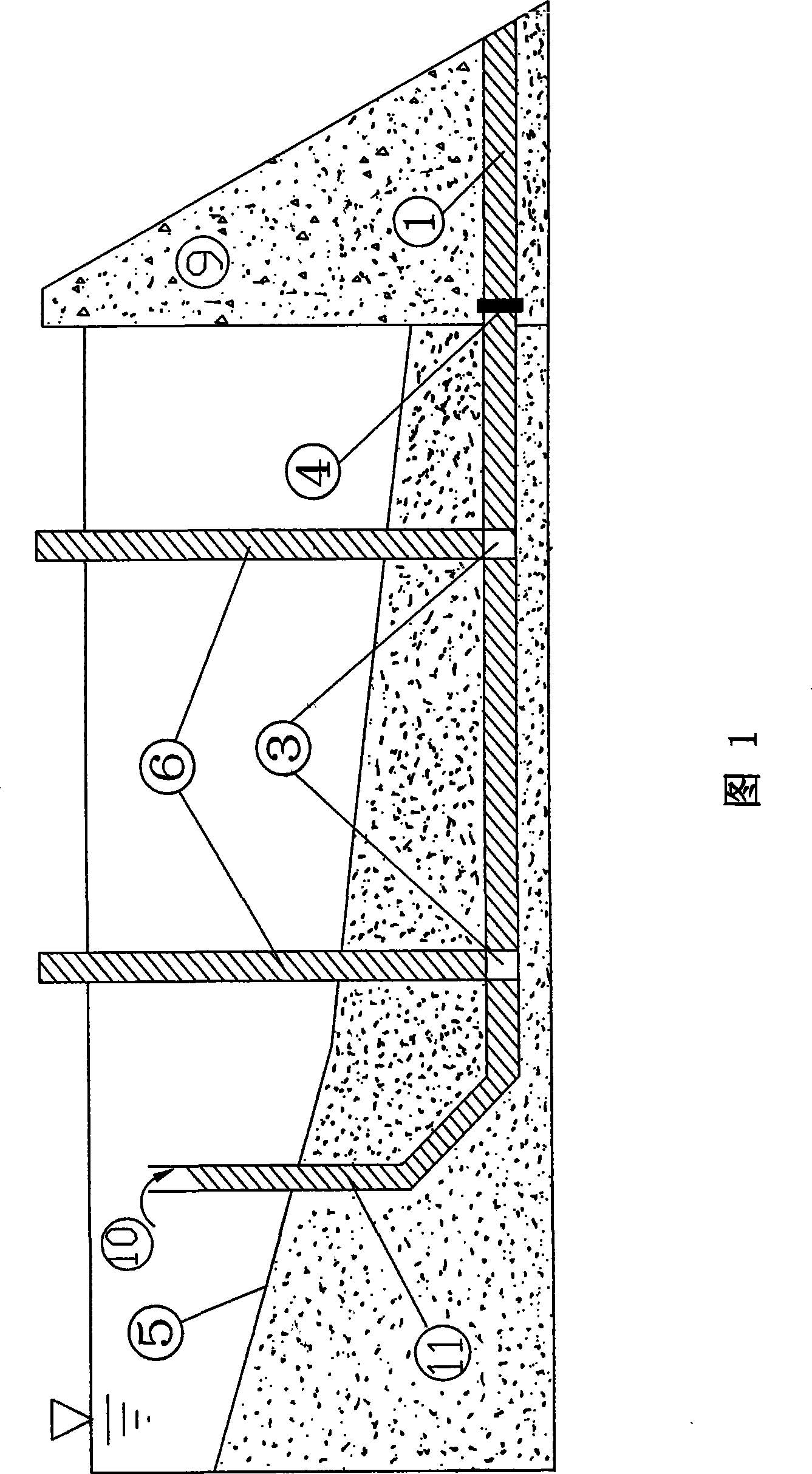
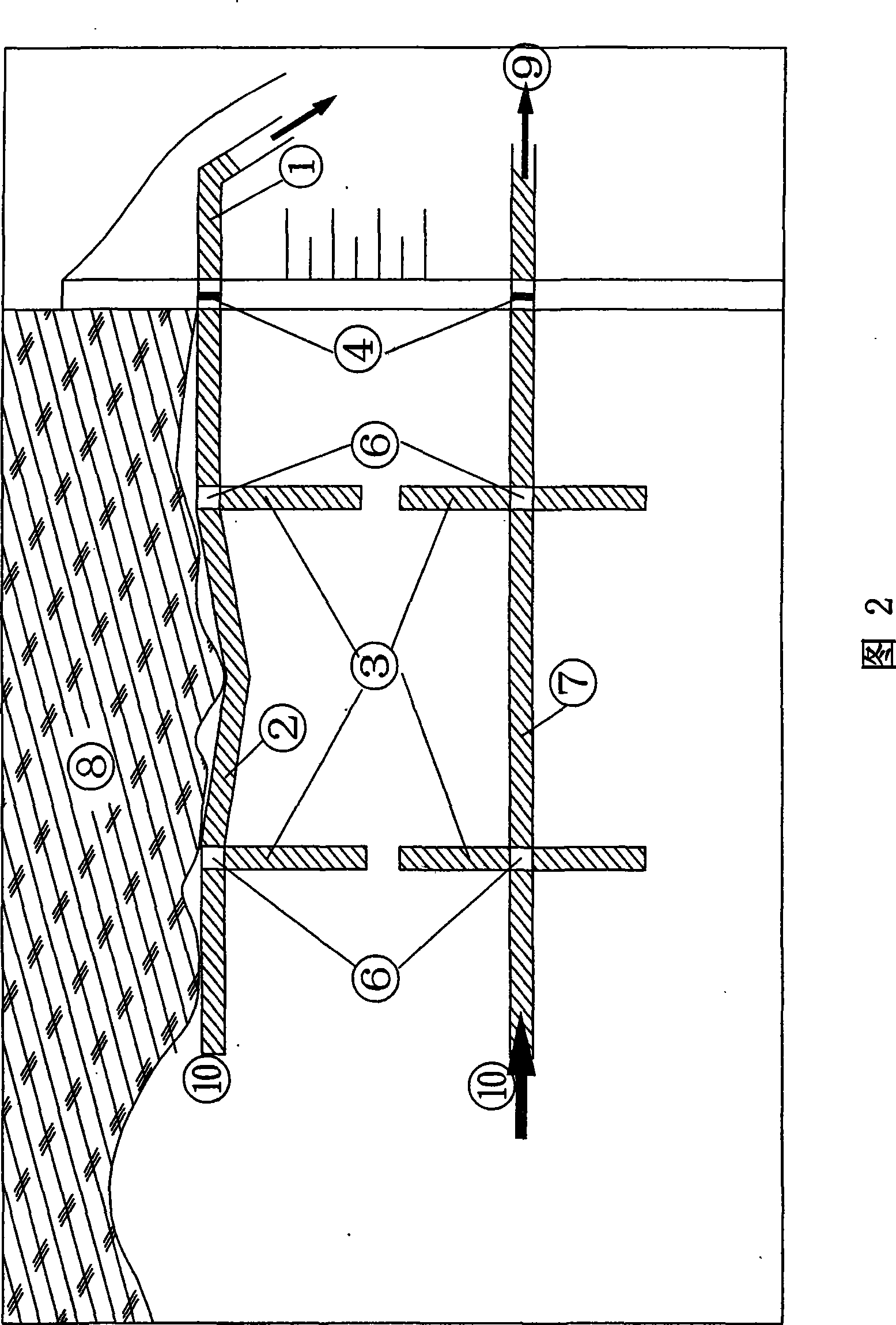
[0019] Embodiment: Referring to Fig. 1 and Fig. 2, in the figure, the tail end of the sand discharge pipeline of the hydraulic arrangement type sand discharge structure is connected with the bottom hole or tunnel 1 of the dam body 9, and a gate valve 4 is set to control the flow and discharge sand The head end of the pipeline extends upstream, and an upwardly curved pipe section is provided at the end, and the upper port 10 of the curved pipe section is higher than the expected sediment deposition surface 5 .

[0020] The quantity of the sand discharge pipeline is two, wherein a sand discharge pipeline 2 is laid on the bank 8 reservoir bottom, and another sand discharge pipeline 7 is laid on the middle reservoir bottom. And, two branch pipes 3 are arranged on one side of the sand discharge pipeline 2, two gate wells 6 are arranged on the upper side pipe wall, and control valves are arranged in the gate valve 6 wells; the two side pipe walls of the sand discharge pipeline 7 Two...


PUM


Abstract

The invention discloses a hydraulic arrangement type sand discharging structure, which comprises sand discharging pipelines, wherein the sand discharging pipelines are laid on the bottom parts of a reservoir, the tail ends of the sand discharging pipelines are connected with a bottom hole or a tunnel of a dam body and provided with gate valves to control the discharge rate; the head ends of the sand discharging pipelines are extended toward up stream, the end parts or proper parts of the sand discharging pipelines are provided with curved pipe segments tilted upward, and upper end openings of the curved pipe segments are higher than the expected sand silting face; and one side or / and two side pipe walls of the sand discharging pipes is / are provided with branch pipelines, the upper side pipe walls are provided with gate wells, and the inside of each gate well is provided with control valves. The number of sand discharging pipelines is more than two, and the sand discharging pipelines are laid on the reservoir bottoms on the bank side and in the middle of the reservoir respectively. The number of the gate wells is more than one, the gate wells are arranged on different positions on the upper side pipe wall of each sand discharging pipeline. In the mode of changing the position of a water inlet of a sand discharging hole of the reservoir, the structure utilizes the distributing type space difference generated in laying the sand discharging pipelines to achieve the aim of widening the range of sand discharging; moreover, the structure also has the advantages of unnecessary external energy, high sand discharging efficiency and good social and economic benefits.

Description

1. Technical field: [0001] The invention relates to a sand discharge structure, in particular to a hydraulic arrangement sand discharge structure, which belongs to the field of structural arrangement methods in the field of water conservancy and hydropower engineering. 2. Background technology: [0002] For reservoirs built on silt-rich rivers, how to efficiently discharge sediment during high water level operation is a major problem. At present, there are contradictions and weaknesses in the common methods such as different gravity flow sand discharge, clear storage and muddy discharge, and open kura sand discharge that rely on dispatching means. Overall, the sand discharge efficiency is low. The main reason is that the discharge layout of the hub and the The arrangement of clear water rivers is the same; even if the arrangement of the reserved bottom hole for sand discharge is adopted, because the water inlet is arranged flush, there is still the fact that the sediment sco...

Claims


Application Information

Patent Timeline
Patent Type & Authority Applications(China)
IPC IPC(8): E02B8/02
Inventor 张金良练继建杨敏
Owner 张金良
Why Eureka
Try Eureka