Micro-crack on site concrete strength detecting method and implementing device thereof

A concrete strength and detection method technology, which is applied in the construction industry, water conservancy engineering, and civil engineering fields, can solve the problems that cannot meet the requirements of aging concrete strength detection, the execution process is complicated, and the detection data is highly discrete.

Inactive Publication Date: 2009-04-29
TONGJI UNIV
View PDF0 Cites 8 Cited by
  • Summary
  • Abstract
  • Description
  • Claims
  • Application Information

AI Technical Summary

Problems solved by technology

The rebound method detects the surface hardness of the structural concrete, and the service time of the concrete is generally required to be between 28 days and 1000 days, which cannot meet the requirements for the strength detection of aged concrete; the core drilling method will cause damage to the structure and weaken the cross section of the structure , affect the bearing capacity and reduce the safety reserve of the structure. At the same time, the implementation process of this method is relatively complicated, and it is not suitable as a rapid on-site detection method; the pull-out method is to use a special tool to pull out the anchor that has been placed in the concrete to measure the compressive strength of the concrete. A test method also causes a certain degree of damage to the structure, and the operation process is relatively complicated, which cannot meet the needs of rapid detection; in addition to the safety problems of the shooting method, it is affected by factors such as gunpowder, gun parts quality, and coarse aggregate in the concrete surface. It is difficult to guarantee the detection accuracy, the discreteness of the obtained detection data is relatively large, and the nail-shooting method is rarely formally applied in domestic projects.

Method used


Image

  • Micro-crack on site concrete strength detecting method and implementing device thereof
  • Micro-crack on site concrete strength detecting method and implementing device thereof
  • Micro-crack on site concrete strength detecting method and implementing device thereof

Examples


Embodiment Construction

[0057] The present invention will be further described below in conjunction with the embodiments shown in the accompanying drawings.

[0058] The invention discloses a concrete strength detection technology on the spot with minimal damage, and relates to an instrument for testing using the method.

[0059] The specific operation is as follows:

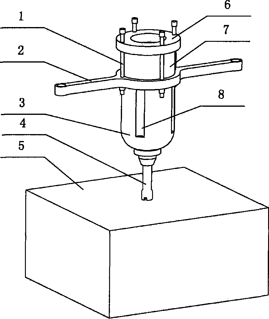
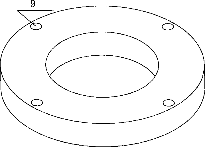
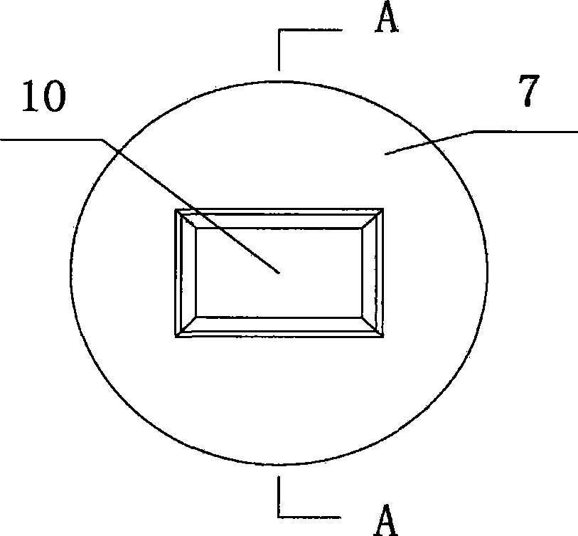
[0060] 1. Assemble the detection device. like Figure 1-Figure 4 As shown, the instrument mainly includes: a drilling rig 3 , a drill bit 4 , a force applying frame and an external force monitor 7 . The external force monitor 7 can be used as a fixed component, or temporarily assembled according to needs, and it is composed of four components: a pressure sensor 11 , a data collector 13 , a liquid crystal display 10 and an external protection device 12 . The pressure sensor 11 is used to monitor the external force acting on the drilling rig; the data collector 13 collects the pressure sensor signal, converts it into pressure, display...


PUM


Abstract

The invention relates to a method for detecting the intensity of concrete of a micro-destructive field and a realization device thereof, and belongs to the field of architectural and civil engineering. The device comprises an aiguille, a drilling machine, a force application rack and an external force monitor; and the external force monitor is arranged on the force application rack and detects the external force applied by the force application rack. In operation, the external force is applied on the force application rack; the drilling machine connected with the force application rack screws in; further the aiguille drills into the concrete to mensurate the drilling aging value; the measure step is repeated for multiple times; the drilling aging values of a plurality of points are mensurated; odd values are eliminated to obtain a mean value; and according to a formula that C is equal to alpha psi h, the intensity of the concrete is obtained. The method has a simple structure and convenient operation and can be applied to the detection of the intensity of the structural concrete with long service time.

Description

technical field [0001] The invention belongs to the fields of construction industry, civil engineering and water conservancy engineering, and relates to concrete strength detection technology. Background technique [0002] Affected by the service environment, the performance and mechanical indexes of the concrete material of the existing building structure will have changes that are not conducive to the service safety of the building structure. The detection of concrete materials of existing building structures is a necessary means to determine the strength of structural concrete and evaluate the service safety of building structures. [0003] In China, the technology or equipment used for on-site testing of concrete strength has certain limitations. The existing destructive testing technology is gradually replaced by new minimally destructive testing technology and non-destructive testing technology due to the damage to the structure. However, it is difficult to meet the ...

Claims


Application Information

Patent Timeline
Patent Type & Authority Applications(China)
IPC IPC(8): G01N3/00G01N33/38
Inventor 姚旭朋刘颖浩迟洋虞春龙柳献
Owner TONGJI UNIV
Why Eureka
Try Eureka