Sheet structure and method of manufacturing the same

A technology of electronic equipment and manufacturing method, which is applied in the direction of lighting and heating equipment, heat exchange equipment, circuits, etc., can solve the problems that carbon nanotubes cannot be fully utilized, high thermal conductivity, etc., to prevent shape changes, increase surface density, and improve Effects of Thermal and Electrical Conductivity

Inactive Publication Date: 2009-04-29
FUJITSU LTD
View PDF6 Cites 5 Cited by
  • Summary
  • Abstract
  • Description
  • Claims
  • Application Information

AI Technical Summary

Problems solved by technology

[0012] However, in the existing heat conduction plates using carbon nanotubes, the high thermal conductivity of carbon nanotubes cannot be fully utilized.

Method used


Image

  • Sheet structure and method of manufacturing the same
  • Sheet structure and method of manufacturing the same
  • Sheet structure and method of manufacturing the same

Examples


no. 1 approach

[0051] Referring to Figure 1A to Figure 7D The carbon nanotube sheet and its manufacturing method of the first embodiment will be described.

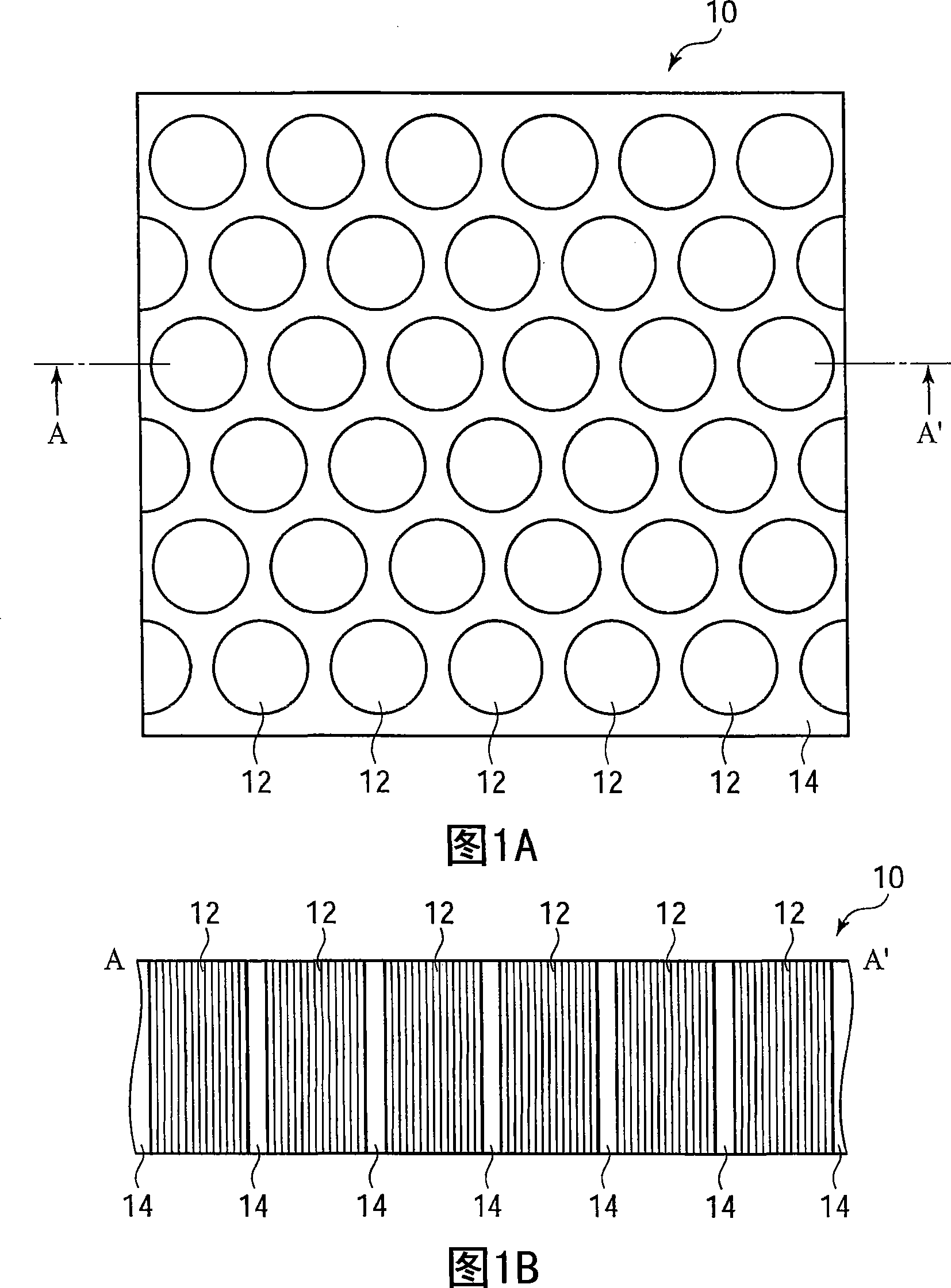
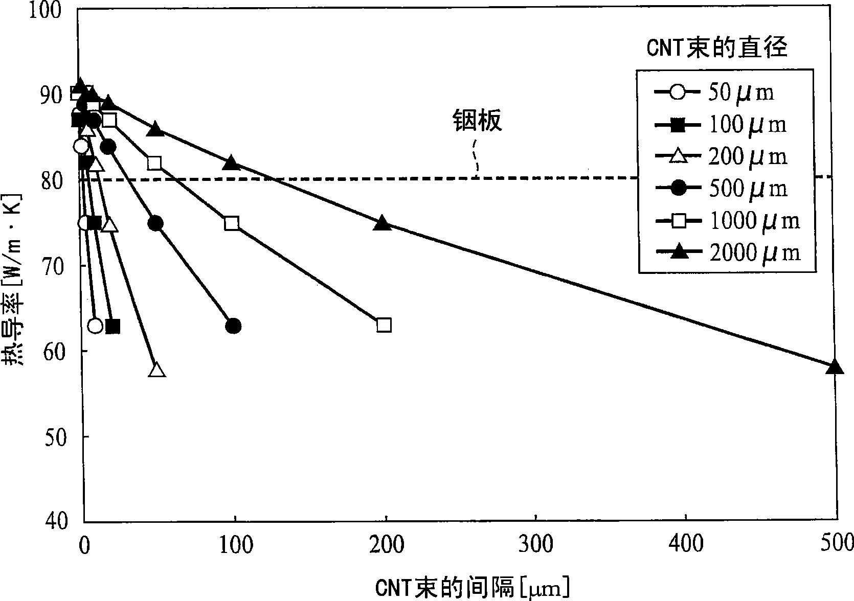
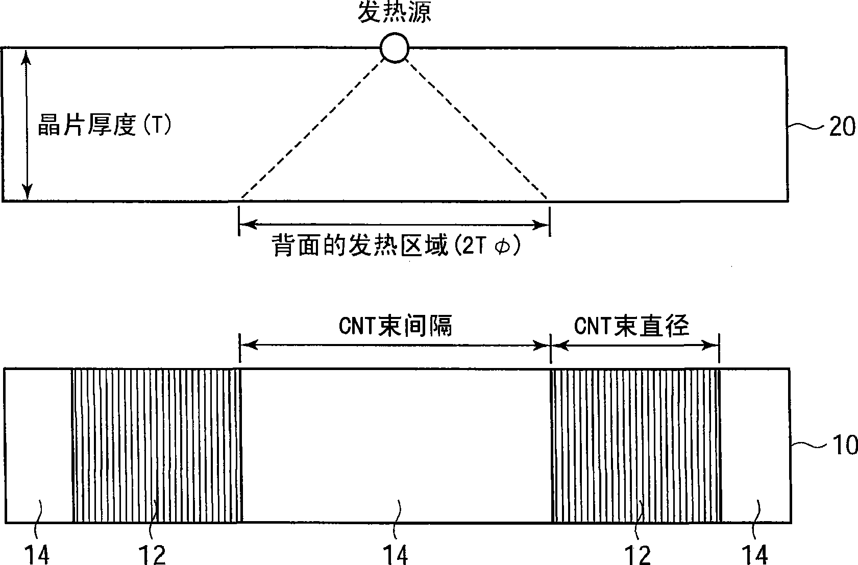
[0052] 1A and 1B are a plan view and a schematic cross-sectional view showing the structure of a carbon nanotube sheet according to the present embodiment. figure 2 It is a graph showing the relationship between the thermal conductivity of the carbon nanotube sheet and the distance between the carbon nanotube bundles of the present embodiment. image 3 It is a figure explaining the suitable spacing of the carbon nanotube bundles of the carbon nanotube sheet of this embodiment. Figure 4A ~ Figure 4E It is a plan view showing the shape of the carbon nanotube bundles of the carbon nanotube sheet of the present embodiment. Figure 5A ~ Figure 5D It is a schematic cross-sectional view showing the structure of the carbon nanotube sheet of the present embodiment. Figure 6A ~ Figure 6D and Figure 7A ~ Figure 7D It is a process sectional...

no. 2 approach

[0110] refer to Figure 8A to Figure 11B The carbon nanotube sheet and its manufacturing method of the second embodiment will be described. Additionally, for and Figures 1A to Figure 7D The same structural elements of the carbon nanotube sheet and its manufacturing method of the first embodiment shown are assigned the same reference numerals and descriptions are omitted or simplified.

[0111] Figure 8A , Figure 8B It is a perspective view and a schematic cross-sectional view showing the structure of the carbon nanotube sheet of the present embodiment. Figure 9A to Figure 11B It is a process sectional view showing the manufacturing method of the carbon nanotube sheet of this embodiment.

[0112] First, refer to Figure 8A , Figure 8B The structure of the carbon nanotube sheet of this embodiment will be described. Figure 8A and Figure 8B These are a perspective view and a cross-sectional view showing the structure of the carbon nanotube sheet of the present embod...

no. 3 approach

[0134] refer to Figures 12A to 14C The carbon nanotube sheet and its manufacturing method of the third embodiment will be described. Additionally, for and Figures 1A to Figure 11B The same structural elements of the carbon nanotube sheets and their manufacturing methods of the first and second embodiments shown are assigned the same reference numerals, and explanations are omitted or simplified.

[0135] Figure 12A , Figure 12B It is a perspective view and a schematic cross-sectional view showing the structure of the carbon nanotube sheet of the present embodiment. Figure 13A ~ Figure 13C and Figure 14A ~ Figure 14C It is a process sectional view showing the manufacturing method of the carbon nanotube sheet of this embodiment.

[0136] First, referring to Figure 12, Figure 12B The structure of the carbon nanotube sheet of this embodiment will be described. Figure 12A and Figure 12B These are a perspective view and a cross-sectional view showing the structure o...


PUM


Abstract

The invention provides a plate structure with heat diffusivity and high electrical conductivity comprising the linear structure of the carbon element and manufacturing method thereof and an electric device using the plate structure. The plate structure has multiple beam linear structure (12), including each other to maintain their space the way the first configuration includes a number of linear carbon structure, and a number of thread-like structures described in beam (12) to each other than the first gap to maintain the second largest allocation of space the way; filler layer (14), filled between the first and the second gap for the structure to maintain a number of linear beams (12).

Description

technical field [0001] The present invention relates to a plate-like structure and a manufacturing method thereof, in particular to a plate-like structure having a linear structure including carbon elements oriented in a direction perpendicular to the plate surface and a manufacturing method thereof, and the use of such a Electronic equipment with a plate-like structure. Background technique [0002] In an electronic component used in a central processing unit (CPU: Central Processing Unit) of a server or a personal computer, it is necessary to efficiently dissipate heat generated by a semiconductor element. Therefore, it has a structure in which a heat spreader made of a material having high thermal conductivity such as copper is provided via a heat conduction plate such as an indium plate provided directly above the semiconductor element. [0003] However, since the price of indium has risen due to a sharp increase in demand for rare metals in recent years, it is desired ...

Claims


Application Information

Patent Timeline
Patent Type & Authority Applications(China)
IPC IPC(8): H05K7/20H01L23/373F28F21/02
CPCH01L23/433H01L24/29H01L2924/04941H01L2224/73204H01L2224/32225H01L2224/73253H01L2224/16H01L2924/16152H01L23/3733H01L23/3735H01L2224/16225H01L23/373H01L2924/01046H01L2924/01019H01L2924/01078H01L2924/01079H01L2924/00011H01L2924/00014H01L2924/15788Y10T428/2462H01L2924/00H01L2224/0401
Inventor 岩井大介近藤大雄山口佳孝曾我育生广濑真一
Owner FUJITSU LTD
Why Eureka
Try Eureka