

Welded flange hot-rolling technique
A flange and process technology, applied in the field of flat welding flange hot coil process, can solve the problems of increased manufacturing cost and workload, unequal thickness of inner and outer diameters, increased operating procedures, etc., to overcome waste of raw materials and accurate geometric dimensions , to avoid the effect of breaking
- Summary
- Abstract
- Description
- Claims
- Application Information
AI Technical Summary
Problems solved by technology
Method used
Image

Examples
Embodiment 1
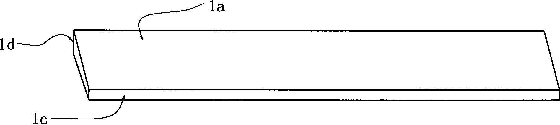
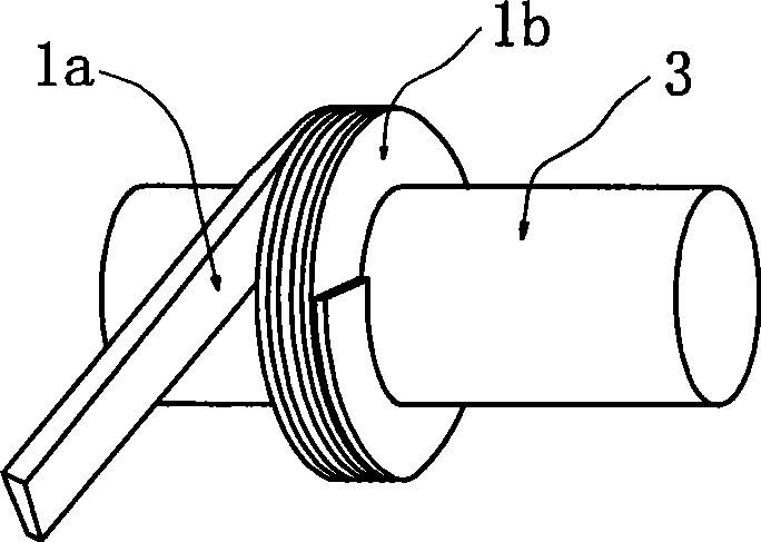
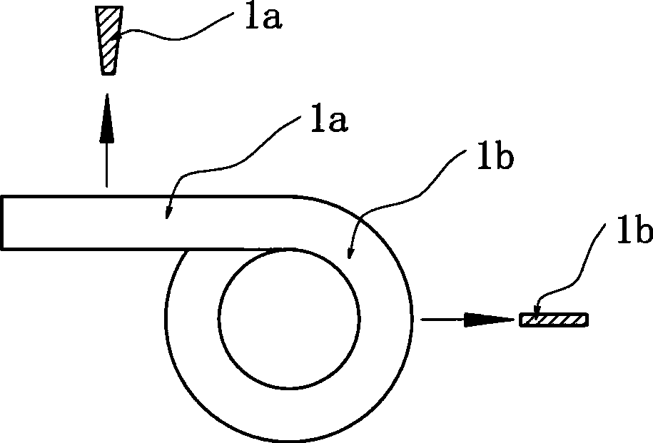
[0030] Embodiment one: see figure 1 , figure 2 , image 3 , Figure 4 , Figure 5-1 , Figure 5-2 , the number 1a in the figure is a strip-shaped hot-rolled flat steel plate, 1b is the round steel ring after hot rolling, 2 is the busbar cutting line of the spiral multi-layer round steel ring, 3 is a cylindrical mold of a certain type, and 4 is The staggered joint after cutting, 5 is the welding seam.
[0031] A flat welding flange hot rolling process, the process steps are:
[0032] (1) The steel billet is heated in a furnace and rolled into the required strip-shaped hot-rolled flat steel plate 1a at a rolling temperature of 1100-1150°C; the steel billet is rolled into a strip-shaped isosceles trapezoidal cross section The hot-rolled flat steel 1a, that is, the strip-shaped hot-rolled flat steel has unequal widths on both sides. The use of hot-rolled flat steel with unequal width on both sides can make the inner and outer thicknesses of the curled round steel rings the...
PUM
 Abstract
Description
Claims
Application Information