
High incidence dissymmetry eddy single-hole site micro-blowing disturbance active control method and device

A technology of active control and air blowing device, which is applied in the direction of aircraft control, transportation and packaging, and affecting the air flow flowing through the surface of the aircraft, etc. It can solve the problems of efficiency reduction, aircraft lateral deviation, lack of lateral controllability, etc.

Inactive Publication Date: 2009-05-06
BEIHANG UNIV
View PDF0 Cites 18 Cited by
  • Summary
  • Abstract
  • Description
  • Claims
  • Application Information

AI Technical Summary

Problems solved by technology

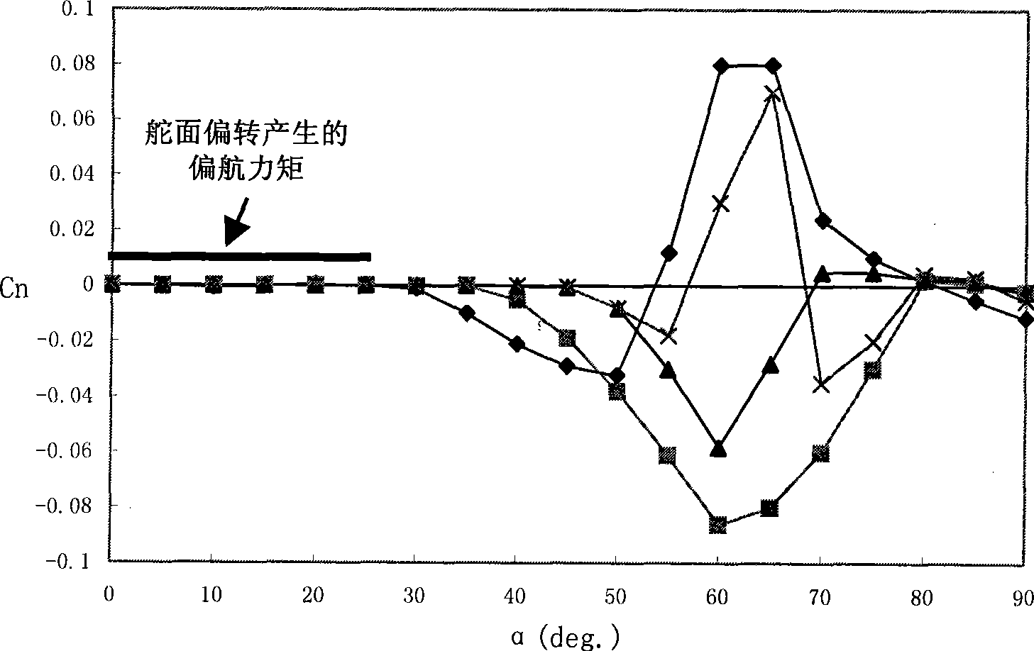
However, the current advanced aircraft basically adopt the front fuselage with the characteristics of a slender spiral body, and the slender spiral body will cause the flow uncertainty due to the uncertain distribution of the processing error at a high angle of attack, and the accompanying large Lateral force, especially the asymmetric swirling flow of the front body at zero sideslip and high angle of attack, will cause complex and sometimes even uncontrollable flight phenomena such as lateral deviation, wing rocking, and downshoot of the aircraft
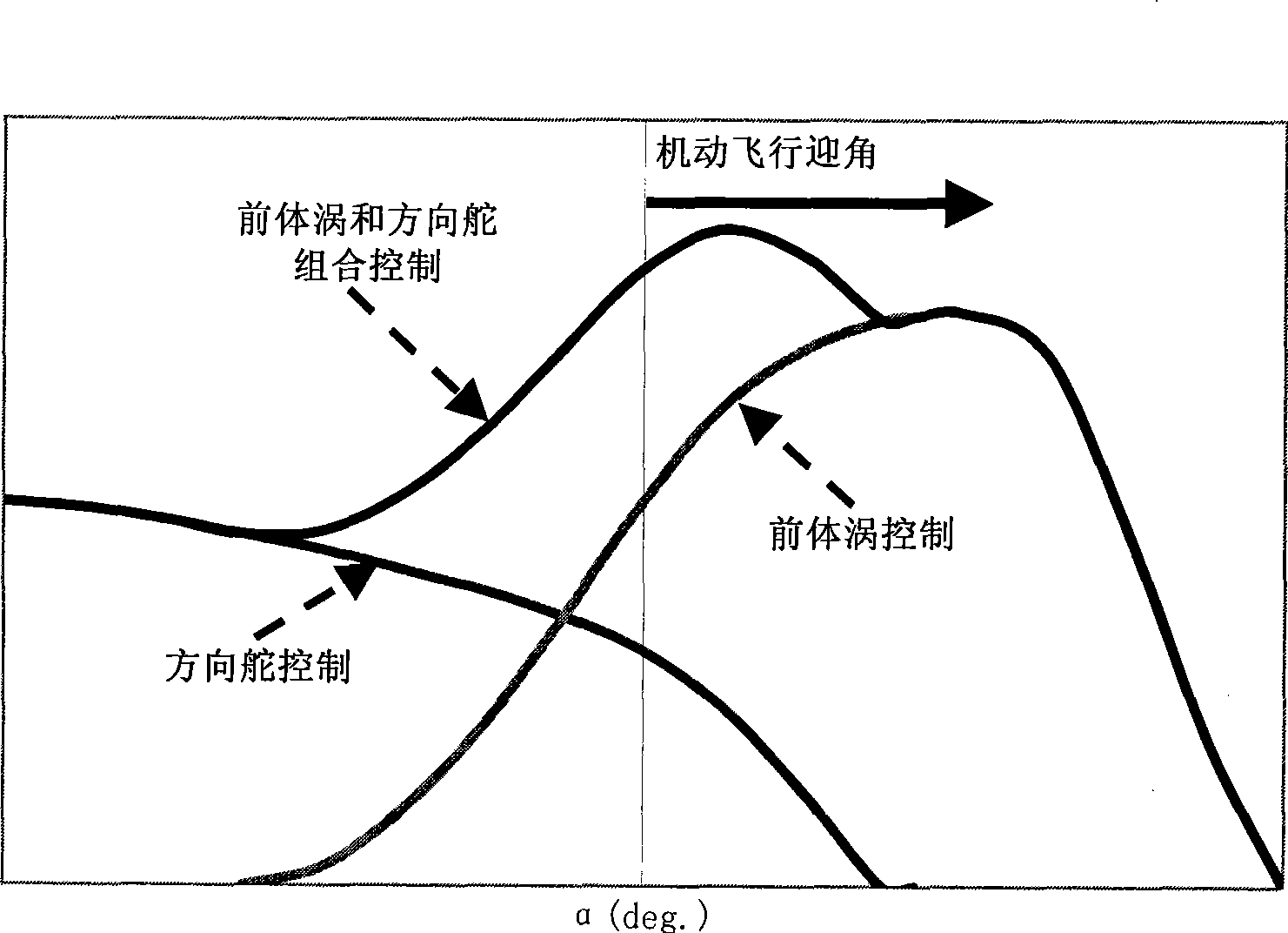
However, at high angles of attack in the post-stall range, the control surfaces (such as the vertical tail and rudder) of the traditional fighter layout are drawn into the separation flow field of the wing, and the efficiency drops sharply, which cannot provide the yaw required by the active control of the aircraft. moments and lateral forces, resulting in a severe lack of lateral controllability of the aircraft in the range of angles of attack for maximum lift and post-stall conditions

Method used


Image

  • High incidence dissymmetry eddy single-hole site micro-blowing disturbance active control method and device
  • High incidence dissymmetry eddy single-hole site micro-blowing disturbance active control method and device
  • High incidence dissymmetry eddy single-hole site micro-blowing disturbance active control method and device

Examples


specific Embodiment approach

[0085] The specific implementation is as follows: please refer to the accompanying drawings;

[0086] , the high-pressure gas (pressure 150Mpa) of the high-pressure nitrogen cylinder is reduced to 0.4-0.6MPa through the pressure reducing valve, and introduced into the single-hole micro-blowing model through the flow meter, pressure gauge and gas pipeline, and blown The air hole hose joint 2.3 introduces the rotatable blowing head 1, and then passes through the 1.3 stainless steel pipe, the air guide hole 1.2 (diameter 0.8mm) and the blowing hole 1.1 (diameter 0.5mm) to blow the control gas into the flow field;

[0087] , the stepper motor driver accepts the rotation angle command issued by the computer, controls the rotation of the stepper motor 2.7, and drives the rotatable blowing head 1 of the single-hole micro blowing model through the coupling 2.4 and the motor rotating shaft 2.2 Rotate to the specified angle position;

[0088] . Adjust the air blowing hole 1.1 in the ...


PUM

PropertyMeasurementUnit
Diameteraaaaaaaaaa

Abstract

The invention relates to a high-incidence asymmetric vortices single-hole micro-blowing positive control method and a corresponding apparatus. The method includes the following steps: step 1. the apparatus is manufactured and prepared well; step 2. the model state and air supply are regulated; and step 3. the lateral force control is carried out. The apparatus comprises a rotary blowing head, a micro-blowing assembly and an air-supply and flow regulating device which is formed by a nitrogen bottle, a pressure-reducing valve, a flow meter, a pressure meter, a gas pipeline and a single-hole micro-blowing model. The pressure of the high-pressure gas in the nitrogen bottle is reduced to 0.4 to 0.6 MPa through the pressure-reducing valve and then the gas is injected through the flow meter, the pressure meter and the gas pipeline into the rotary blowing head of the single-hole micro-blowing model; then the control gas is blown to a flow field through a stainless-steel pipe, a guide vent and a blowing vent so as to control the asymmetric vortices and the blown flow is controlled by regulating the flow meter. The blowing vent on the rotary blowing head is arranged on a position which is away from the head tip of the model by 3mm; and the smaller the distance between the blowing vent and the head tip is, the better the effect is.

Description

(1) Technical field: [0001] The invention relates to an active control method and device for a high-angle-of-attack asymmetric vortex single-hole micro-blowing disturbance and belongs to the technical field of aerospace control. (two) background technology: [0002] For modern fighters and advanced tactical missiles, in order to improve their combat effectiveness, high requirements are usually placed on their flight maneuverability and agility. The high maneuverability and high agility of the aircraft are achieved through high angle of attack flight or even post-stall flight, so high-efficiency combat aircraft must have excellent high angle of attack aerodynamic characteristics. However, due to the large-scale separation flow and complex vortex flow in the flow around the aircraft at high angles of attack, especially the asymmetrical vortex flow of the precursor at zero sideslip and high angle of attack, it will cause the lateral deviation of the aircraft , wing rock, under...

Claims


Application Information

Patent Timeline
IPC IPC(8): B64C17/00B64C21/04
Inventor 邓学蓥王延奎陈学锐田伟马宝锋李岩
Owner BEIHANG UNIV
Learn More