Insulation and collecting well

A technology of collecting well and thermal insulation layer, applied in water supply installations, drinking water installations, buildings and other directions, can solve the problems of difficult construction, complex structure, unsatisfactory thermal insulation effect of seepage pool, etc., and achieve the effect of improving construction speed and being beneficial to environmental protection.

Inactive Publication Date: 2009-05-06
COLD & ARID REGIONS ENVIRONMENTAL & ENG RES INST CHINESE
View PDF0 Cites 4 Cited by
  • Summary
  • Abstract
  • Description
  • Claims
  • Application Information

AI Technical Summary

Problems solved by technology

[0004] In order to overcome the defects of unsatisfactory heat preservation effect, complex structure and difficult construction ...

Method used


Image

  • Insulation and collecting well
  • Insulation and collecting well
  • Insulation and collecting well

Examples


Embodiment Construction

[0030] In order to better understand the present invention, the following examples can be used to further illustrate, but not limit the present invention.

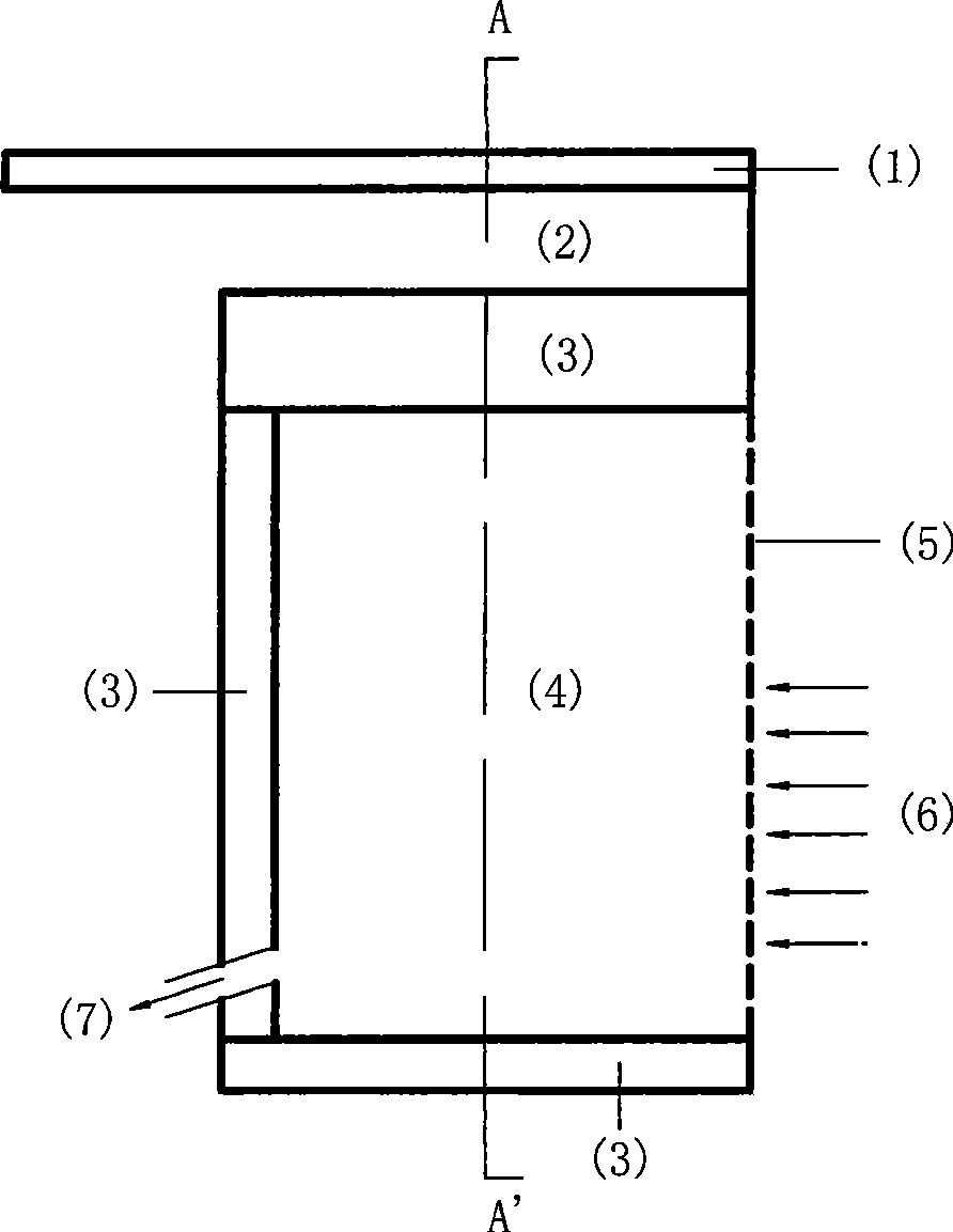
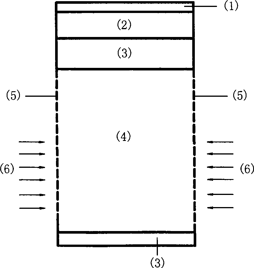
[0031] Such as figure 1 As shown, a thermal insulation water collection well is composed of a turf covering layer 1, a filling layer 2, an insulating layer 3, a block stone layer 4, a permeable geotextile 5, and a water outlet 7. An insulating layer 3 is provided at the bottom of the well wall, the water outlet end of the well head or one side of the well wall, and a permeable geotextile 5 is provided on both sides or one side of the well wall. There is a turf covering layer 1 on the soil layer 2, and the water outlet 7 is connected with the underground drainage pipe.

[0032] Take the heat preservation water collection well adopted at K81+300 of Lamo Highway in Greater Khingan Mountains as an example. Geographical coordinates: N50°47.759′, E120°03.758′. With an altitude of 774m, it belongs to the high latitude cold are...


PUM

PropertyMeasurementUnit
Thicknessaaaaaaaaaa
Thermal conductivityaaaaaaaaaa
Compressive strengthaaaaaaaaaa

Abstract

The invention relates to a heat preservation collecting well, which consists of a turf cover layer, an earth fill layer, heat preservation layers, block stone layers, a water permeable geotextile, and a water outlet. The bottom part of the well, a water outlet end face of a well mouth or the lateral surface of the well wall are provided with the heat preservation layers; two sides or one lateral surface of the well wall is provided with the water permeable geotextile; the block stone layers are stacked in the well; the top part of the well is the earth fill layer; the turf cover layer is above the earth fill layer; and the water outlet is connected with an underground drainage pipe. The heat preservation collecting well uses the water permeable geotextile to replace an inverted filter layer consisting of gravels and block stones of the prior measure to greatly improve construction speed, and uses an extrusion molding polyethylene heat preservation plate to produce double effects of water isolation and heat preservation so that the heat loss in the collecting well is little. The heat preservation collecting well has simple structure, easy and quick construction, and perfect heat preservation effect, is advantageous for drainage, reduces engineering frozen injuries caused by unsmooth drainage in winter, and can be widely applied to underground water collecting and draining systems for projects of highway, railway and the like in cold areas.

Description

technical field [0001] The invention relates to a groundwater collection structure in cold regions. Suitable for underground water collection and drainage systems in cold regions. Background technique [0002] Most of my country's land area is in the cold region. Road engineering and mine engineering in cold regions all involve the collection and discharge of groundwater. The traditional way of collecting groundwater is to collect groundwater in seepage wells and ponds, and then drain it through hidden pipes and blind ditches. Due to the cold winter climate in cold regions, the water collection structure, hidden pipes, and blind ditch are easily frozen and blocked, resulting in the failure of the entire water collection and drainage system and causing damage to the project; the water collection structure mainly relies on increasing the thickness of the soil layer to achieve heat preservation. This method is slow in construction, poor in effect and unfavorable for environm...

Claims


Application Information

Patent Timeline
IPC IPC(8): E03B3/08E03B3/16
Inventor 喻文兵赖远明郭明
Owner COLD & ARID REGIONS ENVIRONMENTAL & ENG RES INST CHINESE
Why Eureka
Try Eureka