Supersonic speed combustion chamber scheme of step / groove composite injection structure

A technology of supersonic combustion chambers and combustion chambers, which is applied in the direction of combustion chambers, combustion methods, continuous combustion chambers, etc., can solve the problems that have not been raised, and achieve the effects of stable combustion, stable flame, and small total pressure loss

Inactive Publication Date: 2009-05-20
周建兴 +1
View PDF0 Cites 20 Cited by
  • Summary
  • Abstract
  • Description
  • Claims
  • Application Information

AI Technical Summary

Problems solved by technology

However, there is no new proposal on how to make full use of the flame stabilization effect of the groove structure, and how to combine the f

Method used


Image

  • Supersonic speed combustion chamber scheme of step / groove composite injection structure
  • Supersonic speed combustion chamber scheme of step / groove composite injection structure
  • Supersonic speed combustion chamber scheme of step / groove composite injection structure

Examples


Embodiment Construction

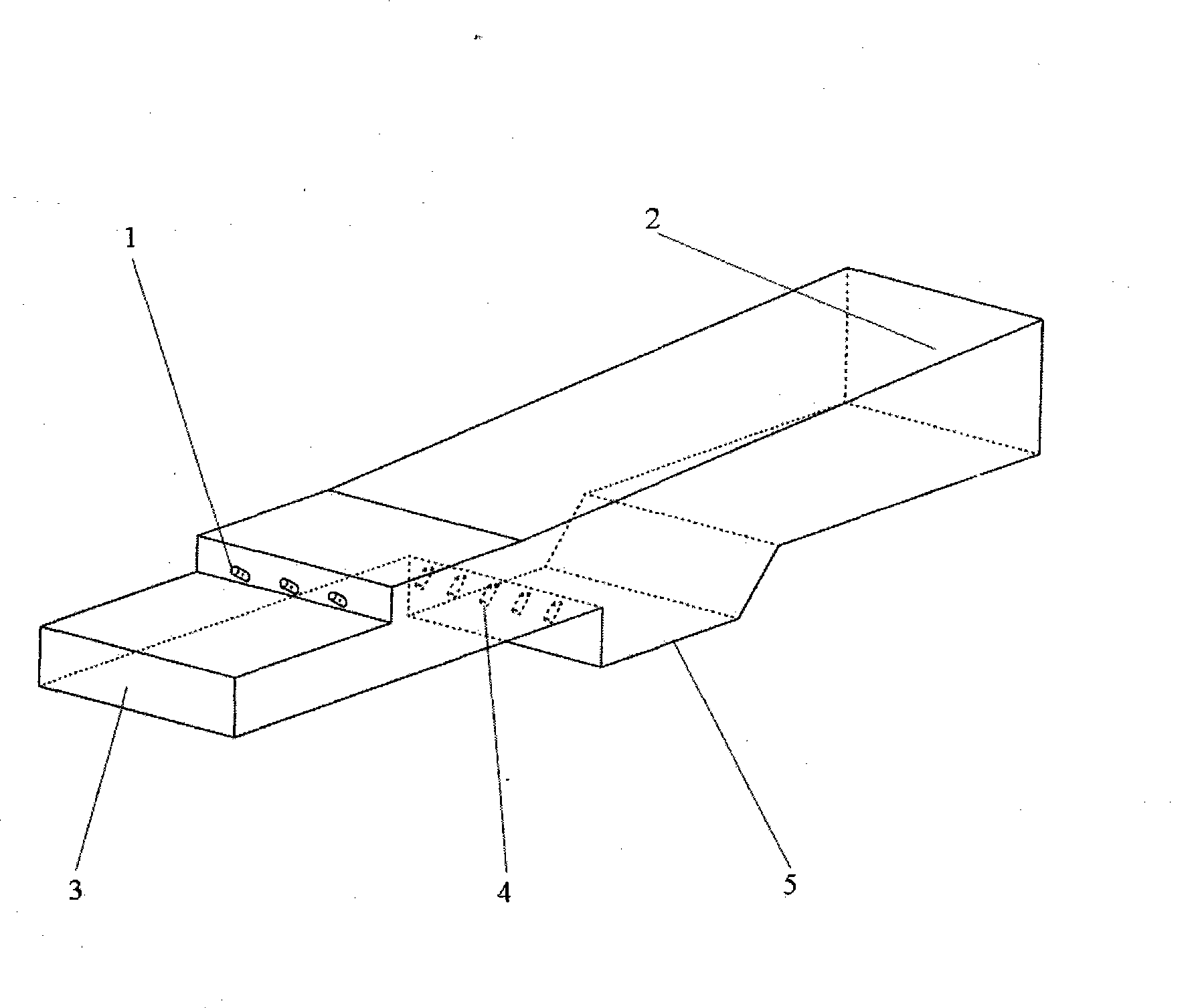
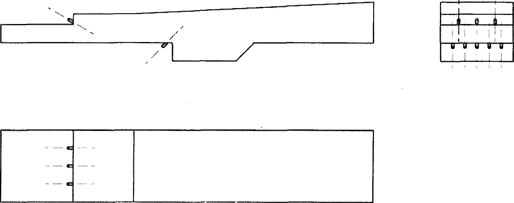
[0028]The specific implementation of the supersonic combustion chamber scheme of the step / groove composite injection structure proposed in this patent can be carried out according to the following design process. When designing the actual combustion chamber structure, according to the specific design requirements, the injection structure before the step, the groove and the layout of the injection structure before the groove should be appropriately modified and designed, and researched with a certain scale of numerical calculation simulation After the analysis, the design idea and scheme of the fuel nozzle are applied to the structural scheme of the designed supersonic combustor. In this way, on the one hand, it can reduce the problem that a large amount of research and development funds need to be invested in the initial stage of research and design in the traditional design work in the past; To a large extent, the structural size of the supersonic combustion chamber can be re...


PUM


Abstract

The innovation of the invention is to provide a proposal for an ultrasonic velocity combustion chamber with a novel step/groove composite jet structure. The proposal is characterized in that fuel nozzles are additionally arranged in the front of a step and a groove of the combustion chamber and are jointly used for fuel jet and use in the combustion chamber. In the design proposal, design proposals of a jet structure of the step and a fuel nozzle structure in the front of the groove are applied in the ultrasonic velocity combustion chamber, and correspondingly improved types of the ultrasonic combustion chambers thereof. The proposal of the designed composite jet structure can ensure evenly jetting of fuel in the ultrasonic velocity combustion chamber, and achieve full mixing of the fuel and air in a low-speed flowing area in the combustion chamber, so as to ensure ignition and stable combustion of the fuel in ultrasonic velocity air flow. Compared with the proposal of a nozzle in the prior ultrasonic velocity combustion chamber, total pressure in the combustion chamber has little loss, thereby shortening structural size of the ultrasonic velocity combustion chamber, improving performance of the whole ultrasonic power system, and having considerable potential economic benefit and value. The proposal for the ultrasonic velocity combustion chamber mainly comprises designs of parts such as the step jet structure in the combustion chamber, the groove, the jet structure in the front of the groove.

Description

1. Technical field [0001] One of the key technologies of scramjet and sub-combustion ramjet is to adopt effective combustion chamber and fuel injection structure, inject fuel into the combustion chamber better, and realize the full mixing of fuel and air as soon as possible, in the shortest possible time Combustion is realized in the combustion chamber space, so that the fuel fully releases chemical energy, which is converted into heat energy of the airflow, and further converted into kinetic energy of the engine power system. However, it should be noted that in the combustion chamber of these engines, the velocity of the airflow is generally very high, the residence time of the airflow in the combustion chamber is very short, often on the order of milliseconds, and the space for fuel mixing is also very limited. Therefore, the injection, ignition and stable combustion of fuel become the key issues to be solved in the combustion of these ramjet power systems. However, in the ...

Claims


Application Information

Patent Timeline
IPC IPC(8): F23R3/34
Inventor 周建兴朴英
Owner 周建兴
Why Eureka
Try Eureka