Sputtering and forming device by tumbling cylinder method

A roller method and sputtering technology, which is applied in the field of rapid solidification and near-net shape processing, can solve the problems of unsuitability for industrial continuous production, difficulty in uniform deposition of molten metal, and single product preparation, so as to facilitate continuous production, convenient implementation, and The effect of simple process equipment

Inactive Publication Date: 2009-05-27
INNER MONGOLIA UNIV OF SCI & TECH
View PDF0 Cites 1 Cited by
  • Summary
  • Abstract
  • Description
  • Claims
  • Application Information

AI Technical Summary

Problems solved by technology

[0004] 1) The preparation product is single, only large rings or tube blanks can be prepared
[0005] 2) It is difficult to ach

Method used


Image

  • Sputtering and forming device by tumbling cylinder method
  • Sputtering and forming device by tumbling cylinder method
  • Sputtering and forming device by tumbling cylinder method

Examples


Embodiment 1

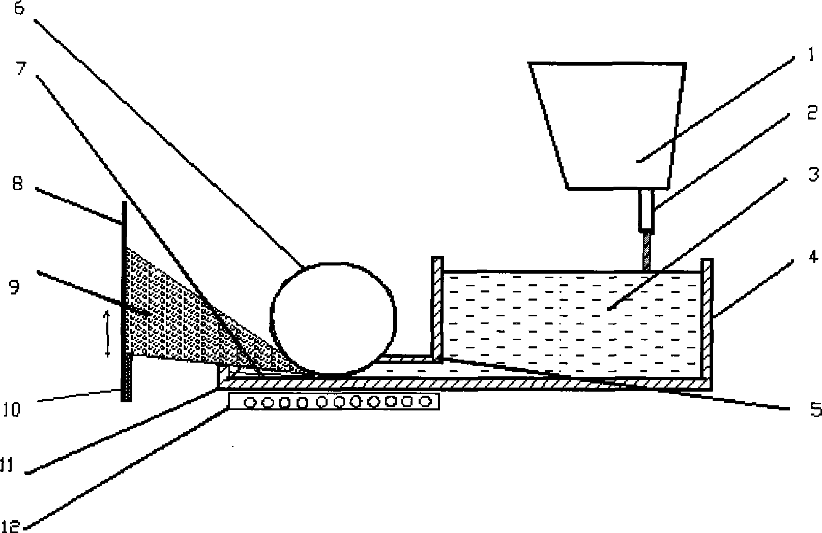
[0027] refer to figure 1 The present invention comprises: a ladle 1, a nozzle 2, a molten metal 3, a tundish 4, a deposition substrate 8, a metal droplet 9, a deposition blank 10, a molten metal drainage channel 5 is provided at the bottom of the tundish 4, and a molten metal drainage There is a high-temperature drum 6 at the exit of the channel 5, and there is a gap between the high-temperature drum 6 and the bottom plate of the molten metal drainage channel 5, and the molten metal 3 in the gap between the high-temperature drum 6 and the bottom end of the molten metal drainage channel 5 forms a liquid steel film 7, and the molten metal is drained A baffle plate 11 is provided at the front end of the bottom plate of the channel 5 , a heater 12 is provided on the lower surface of the bottom plate of the molten metal drainage channel 5 , and the deposition substrate 8 is located on the side of the tundish 4 in front of the high-temperature drum 6 .

[0028] During preparation, i...

Embodiment 2

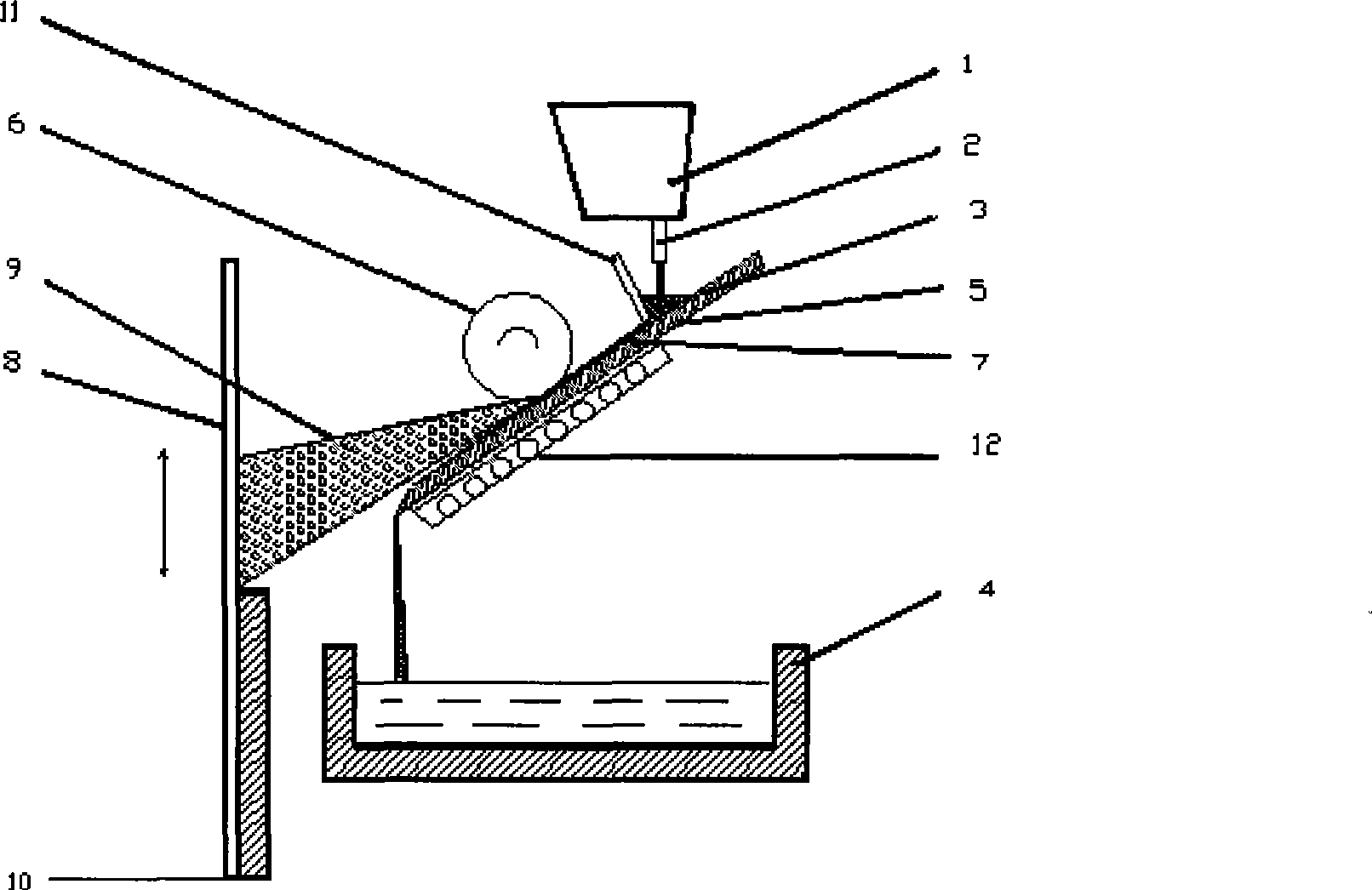
[0030] refer to figure 2 : Including: ladle 1, nozzle 2, molten metal 3, tundish 4, deposition substrate 8, metal droplet 9, deposition blank 10, below the nozzle 2 and above the tundish 4, a prefabricated liquid film is arranged obliquely Plate 13, a baffle plate 14 is arranged above the liquid film prefabricated plate 13, and the baffle plate 14 and the liquid film prefabricated plate 13 form a molten pool. A gap is left to form a liquid film 7 in the gap position of the molten metal 3. In order to prevent the liquid film 7 from solidifying during the flow process, a heater 12 is provided on the lower surface of the bottom plate of the molten metal drainage channel 5, and the deposition substrate 8 It is located on the side of the tundish 4 in front of the high-temperature drum 6 . There is a gap between the high-temperature drum 6 and the bottom plate of the drainage channel 5 of the molten metal 3 .

[0031] The molten steel 4 in the tundish of the present invention is ...

Embodiment 3

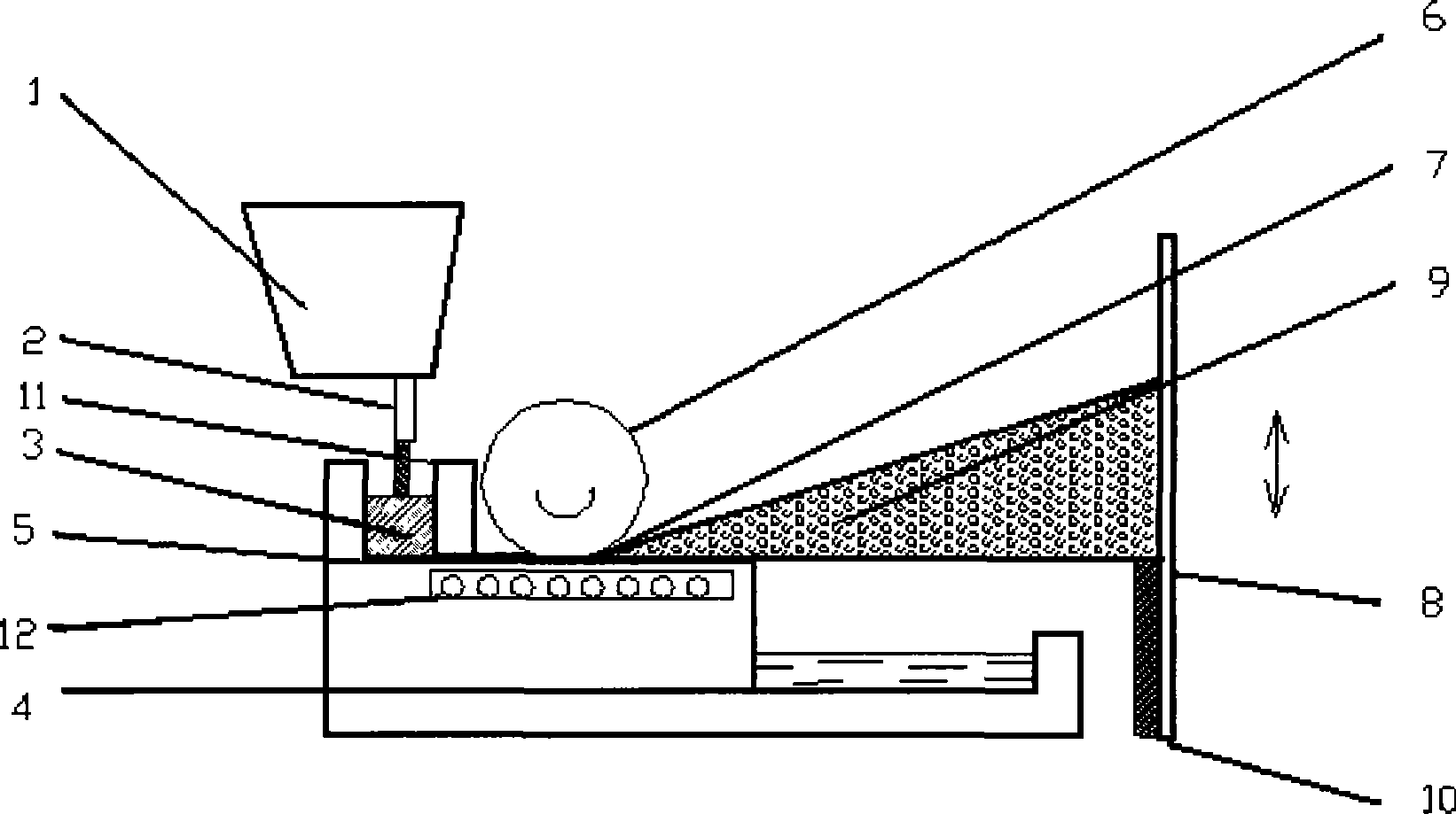
[0033] refer to image 3 : The upper end of the tundish 4 is equipped with a horizontally placed liquid film prefabricated plate 13, a baffle plate 14 is arranged above the liquid film prefabricated plate 13, there is a gap between the baffle plate 14 and the liquid film prefabricated plate 13, and a high temperature is provided in front of the baffle plate 14. Drum 6 , heater 12 is provided on the lower surface of liquid film prefabricated plate 13 located under high temperature drum 6 , and deposition substrate 8 is located on the side of tundish 4 in front of high temperature drum 6 .

[0034] image 3 It is a schematic diagram of the heater-embedded drum method sputtering forming process. The molten metal 9 of the present invention is pre-injected into the molten pool between the liquid film prefabricated plate 13 and the baffle plate 14, and a heater 12 is embedded in the bottom of the liquid film prefabricated plate 13 to prevent the molten metal 3 from solidifying. Th...


PUM


Abstract

The invention relates to a sputtering forming technology by a rotating-drum method and a device thereof, belonging to the fast solidifying and near net-shape forming field in metallurgy of iron and steel. The invention is characterized in that the bottom of a pouring box is provided with a molten metal drainage passage; a port of the molten metal drainage passage is provided with a high temperature roller; a gap is reserved between the high temperature roller and a soleplate of the molten metal drainage passage; the front end of the soleplate of the molten metal drainage passage is provided with a baffle; the lower surface of the soleplate of the molten metal drainage passage is provided with a heater; and a sediment baseplate is arranged at the lateral side of the pouring box in front of the high temperature roller. The invention can prepare deposited blanks including plate, tube blank, composite processing piece and the like; the surface of a deposited layer is uniform; the tissue of a prepared ingot blank is more uniform; the device can prepare metal material with very thin crystal grain; and the technology has simple equipment and is convenient for continuous production.

Description

1. Technical field [0001] The invention relates to a roller sputtering forming process and device, belonging to the field of rapid solidification and near-net shape processing in iron and steel metallurgy. 2. Background technology [0002] The technology of pulverizing molten metal particles for deposition belongs to the field of rapid solidification technology, and centrifugal jet deposition is one of the technologies. The principle of centrifugal spray deposition is: after the molten steel is melted in the crucible, it is transported out through the bottom catheter, and the molten steel drops onto the centrifugal deposition plate at the bottom, and the deposition plate rotates at high speed to centrifugally atomize the metal liquid, and the metal liquid The drop cools rapidly during the flight, and the semi-solid atomized particles are finally deposited on the cold substrate. The substrate moves up and down in the furnace body, and the continuously deposited particles are ...

Claims


Application Information

Patent Timeline
IPC IPC(8): B22D23/00
Inventor 张胤
Owner INNER MONGOLIA UNIV OF SCI & TECH
Why Eureka
Try Eureka