Film forming method and film forming apparatus

A film-forming method and a film-forming device technology, which are applied in the direction of gaseous chemical plating, coating, electrical components, etc., can solve problems such as increased maintenance frequency, and achieve the effect of inhibiting the mixing of impurity elements

Inactive Publication Date: 2009-06-03
TOKYO ELECTRON LTD
View PDF3 Cites 19 Cited by
  • Summary
  • Abstract
  • Description
  • Claims
  • Application Information

AI Technical Summary

Problems solved by technology

[0011] In addition, in the case of forming a tungsten nitride film, a large amount of, for example, NH 4 F and other reaction by-products, maintenance frequency will increase significantly

Method used


Image

  • Film forming method and film forming apparatus
  • Film forming method and film forming apparatus
  • Film forming method and film forming apparatus

Examples


no. 1 approach

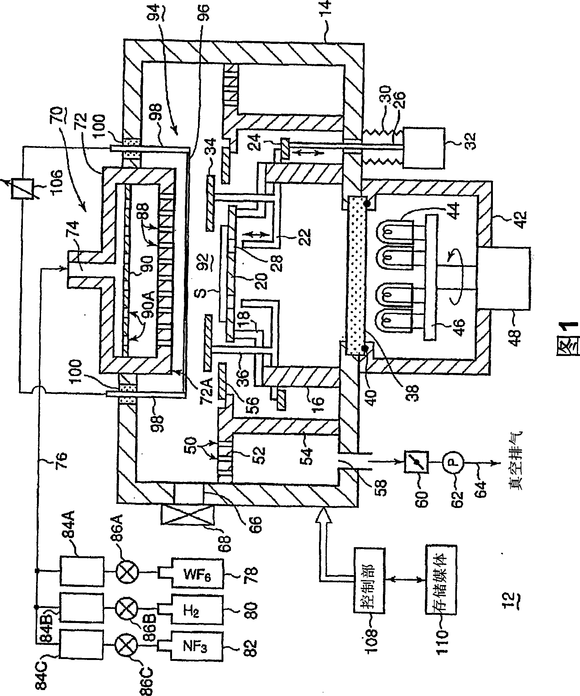
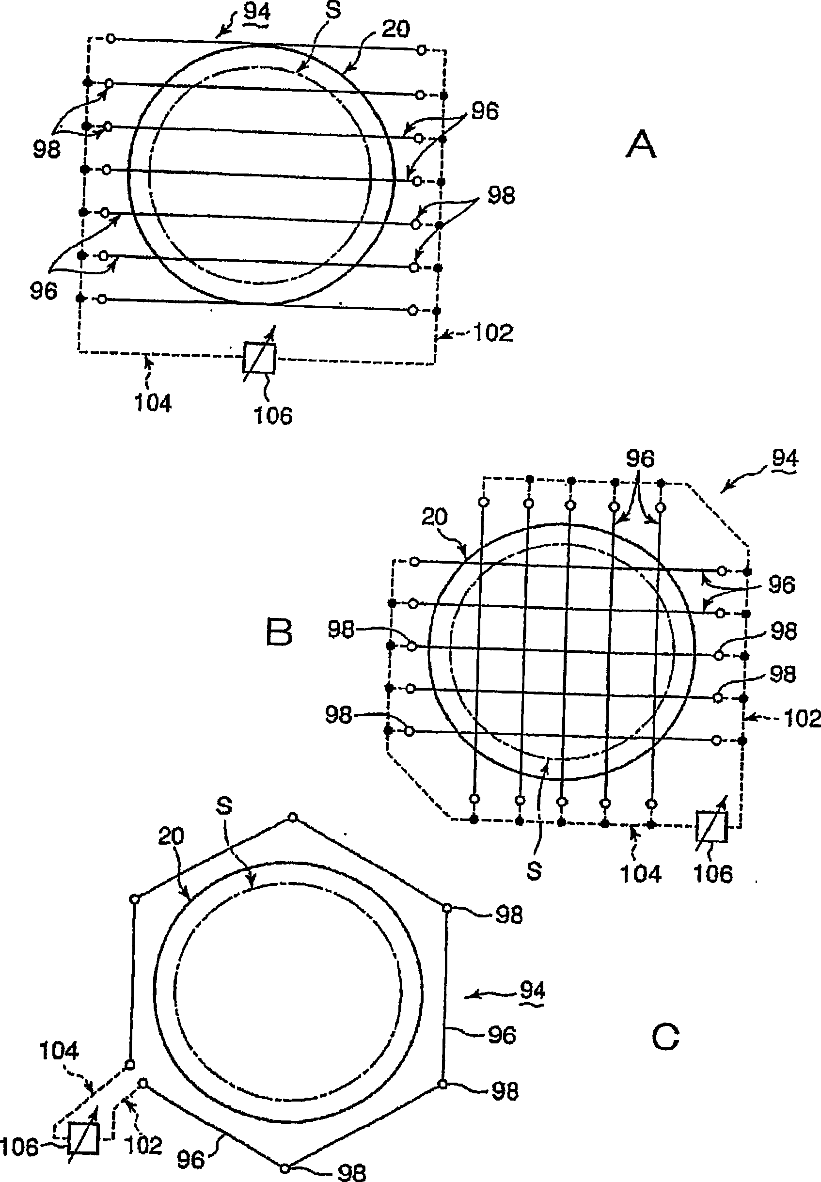
[0043]FIG. 1 is a schematic configuration diagram showing a first embodiment of a film forming apparatus of the present invention. figure 2 A~ figure 2 C is a plan view showing an arrangement example of catalyst bodies, respectively. The film forming apparatus 12 of this embodiment is an apparatus for forming a tungsten (W) film.

[0044] As shown in FIG. 1 , the film forming apparatus 12 has a cylindrical or box-shaped processing container 14 made of, for example, an aluminum alloy or the like. Inside the processing container 14 are provided a pillar 16 rising from the bottom of the container, and a mounting table 20 provided on the pillar 16 via a holding member 18 having, for example, an L-shaped cross section. A semiconductor wafer S as an object to be processed is placed on the stage 20 . The pillar 16 and the holding member 18 are made of a heat-ray transparent material such as quartz. In addition, the mounting base 20 is made of a carbon material, an aluminum comp...

no. 2 approach

[0085] In the first embodiment described above, the case where the tungsten film is formed has been described as an example, but the present invention is also applicable to the case where the tungsten nitride film (WN) is formed instead of the tungsten film.

[0086] In this case, in the film forming apparatus shown in FIG. 1 , a nitriding gas may be used instead of a reducing gas. Specifically, without setting storage H 2 Instead, a nitriding gas source (not shown) for storing nitriding gas is provided instead. In this case, N can be used 2 gas as a nitriding gas. Here, if the N used for purging is used directly 2 gas, there is no need to separately set up a nitriding gas source.

[0087] In this case, the deposited film type is changed from a tungsten film to a tungsten nitride film. Others exhibit the same effects as those described in the first embodiment. That is, in the second embodiment, instead of using the reducing gas, only the nitriding gas, that is, N 2 Gas ...


PUM

PropertyMeasurementUnit
thicknessaaaaaaaaaa

Abstract

The present invention provides a film forming method with a step of placing a subject to be processed in a processing container which can be vacuumized by exhaustion, and a film forming step wherein a tungsten film is formed on the surface of the subject by supplying a tungsten containing gas and a reducing gas into the processing container and activating the reducing gas by a heated catalytic body.

Description

technical field [0001] The invention relates to a film forming method and a film forming device of a tungsten film or a tungsten nitride film. Background technique [0002] In general, in the manufacturing process of a semiconductor integrated circuit, W (tungsten), WN ( Tungsten nitride), WSi (tungsten silicide), Ti (titanium), TiN (titanium nitride), TiSi (titanium silicide) or other metals or metal compounds are deposited to form a thin film. [0003] For the purpose of improving the adhesiveness with the lower layer, a barrier film may be formed as a base of the metal thin film. As the barrier film, a tungsten nitride film and a titanium nitride film are used. Here, a case where a tungsten film is formed as a metal thin film will be described as an example. In the case of forming a tungsten film, generally WF 6 (Tungsten hexafluoride) gas (JP-A-6-89873 and JP-A-2003-96567). [0004] A general film-forming apparatus for forming a metal thin film as described above is...

Claims


Application Information

Patent Timeline
Patent Type & Authority Applications(China)
IPC IPC(8): C23C16/14C23C16/34H01L21/28H01L21/285
CPCC23C16/45544C23C16/45525H01L21/28556C23C16/14C23C16/34H01L21/28H01L21/285
Inventor 立花光博西森崇
Owner TOKYO ELECTRON LTD
Why Eureka
Try Eureka