
1.55 mum wavelength high precision fiber gyroscope for eliminating dead zone

A fiber optic gyroscope and high-precision technology, which is applied in the field of fiber optic gyroscopes, can solve the problems of reducing the random walk performance of fiber optic gyroscopes, and achieve the effects of reducing the influence of coupling, high precision, and improving strength

Active Publication Date: 2010-05-12
BEIJING AEROSPACE TIMES OPTICAL ELECTRONICS TECH
View PDF2 Cites 0 Cited by
  • Summary
  • Abstract
  • Description
  • Claims
  • Application Information

AI Technical Summary

Problems solved by technology

Therefore, the method of random modulation reduces the random walk performance of the fiber optic gyroscope

Method used


Image

  • 1.55 mum wavelength high precision fiber gyroscope for eliminating dead zone
  • 1.55 mum wavelength high precision fiber gyroscope for eliminating dead zone

Examples


Embodiment Construction

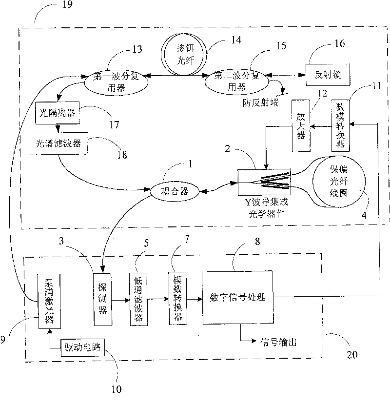
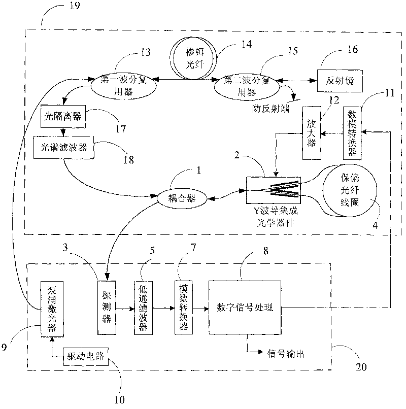
[0018] Such as figure 1 Shown is a schematic diagram of the composition of the fiber optic gyroscope of the present invention, including an optical path unit 19 and a circuit unit 20, wherein the circuit unit 20 includes a laser 9, a laser drive circuit 10, a detector 3, a low-pass filter 5, and an analog-to-digital converter 7 And digital signal processing circuit 8; Optical path unit 19 comprises spectral filter 18, optical isolator 17, the first wavelength division multiplexer 13, erbium-doped optical fiber 14, the second wavelength division multiplexer 15, mirror 16, coupler 1. Y waveguide integrated optical device 2, fiber optic coil 4, digital-to-analog converter 11 and amplifier 12. The optical path unit 19 and the circuit unit 20 are realized by two independent metal boxes, wherein the digital-to-analog converter 11 and the amplifier 12 are on a separate circuit board, and the circuit board and the Y-waveguide integrated optical device 2 are fixed on the metal copper b...


PUM


Abstract

A high-precision optical gyroscope with 1.55 um wavelength for eliminating dead area, comprising a light path unit and a circuit unit; wherein the circuit unit comprises a laser, a laser driving circuit, a detector, a low pass filter, a analog-to-digital converter and a digital signal processing circuit; the light path unit comprises a spectral filter, an optoisolator, a first wavelength divisionmultiplexer, an Er-doped fiber, a second wavelength division multiplexer, a reflector, a coupler, a Y-waveguide integrated optical device and a fiber coil; the spectral filter outputs superfluorescence with 1.55 um wave band; the light path unit further comprises a digital-analog converter and an amplifier; the digital-analog converter, amplifier and Y-waveguide integrated optical device are packed together by a metal box to form electromagnetic shielding. The invention interferes with the electron between driving signal of the Y-waveguide integrated optical device and the signal received by the detector on the structure to isolate, thereby eliminating the dead area caused by interference.

Description

technical field [0001] The invention relates to a fiber optic gyroscope, in particular to a high-precision fiber optic gyroscope using a wavelength of 1.55 μm. Background technique [0002] The interferometric fiber optic gyroscope is an all-solid-state inertial instrument, which has the advantages of high reliability and long life. High-precision fiber optic gyroscopes (with an accuracy better than 0.01° / h) usually use erbium-doped fiber optic light sources with an average wavelength of 1.55 μm . In principle, the fiber optic gyroscope includes two units, the optical path and the circuit. Usually, the optical path unit and the circuit unit are assembled and packaged in the same structure. In order to improve performance, the researchers proposed an assembly form in which the optical unit and the circuit unit are isolated. For a high-precision fiber optic gyroscope with a wavelength of 1.55 μm, the optical unit mainly includes an erbium-doped fiber light source, a coupler, ...

Claims


Application Information

Patent Timeline
Patent Type & Authority Patents(China)
IPC IPC(8): G01C19/72
Inventor 王巍王学锋高峰于海成付铁刚黄磊李晶
Owner BEIJING AEROSPACE TIMES OPTICAL ELECTRONICS TECH
Learn More