
Ion beam pole axis processing method capable of eliminating optical element local error

A technology of optical components and processing methods, which is applied in the field of ion beam polar axis processing of optical components, and can solve problems such as reducing motion system requirements, limiting applications, and inability to repair mirror surfaces.

Inactive Publication Date: 2009-06-17
NAT UNIV OF DEFENSE TECH
View PDF0 Cites 5 Cited by
  • Summary
  • Abstract
  • Description
  • Claims
  • Application Information

AI Technical Summary

Problems solved by technology

The existing polar axis motion method can only repair the rotational symmetry error of the mirror surface, which limits its application in the process and cannot fundamentally reduce the requirements of the motion system
The reason why the existing polar axis motion processing method cannot repair the local error of the mirror surface is that this kind of method first assumes that the error of the mirror surface has the characteristic of rotational symmetry, and the rotational motion of the mirror surface and the linear motion of the ion source cannot reflect the Specular local features

Method used


Image

  • Ion beam pole axis processing method capable of eliminating optical element local error
  • Ion beam pole axis processing method capable of eliminating optical element local error
  • Ion beam pole axis processing method capable of eliminating optical element local error

Examples


Embodiment

[0038] The ion beam polishing process of the present embodiment is carried out on an ion beam polishing equipment (KDIFS-500 type can be selected), and the process parameters are set to: the working gas is argon, and the working vacuum is 0.8×10 -2 Pa, ion energy 1100eV, beam current 25mA. The polished test piece is ordinary glass-ceramics with a diameter of 100mm.

[0039] Carry out ion beam polishing to above-mentioned glass ceramics by following method step:

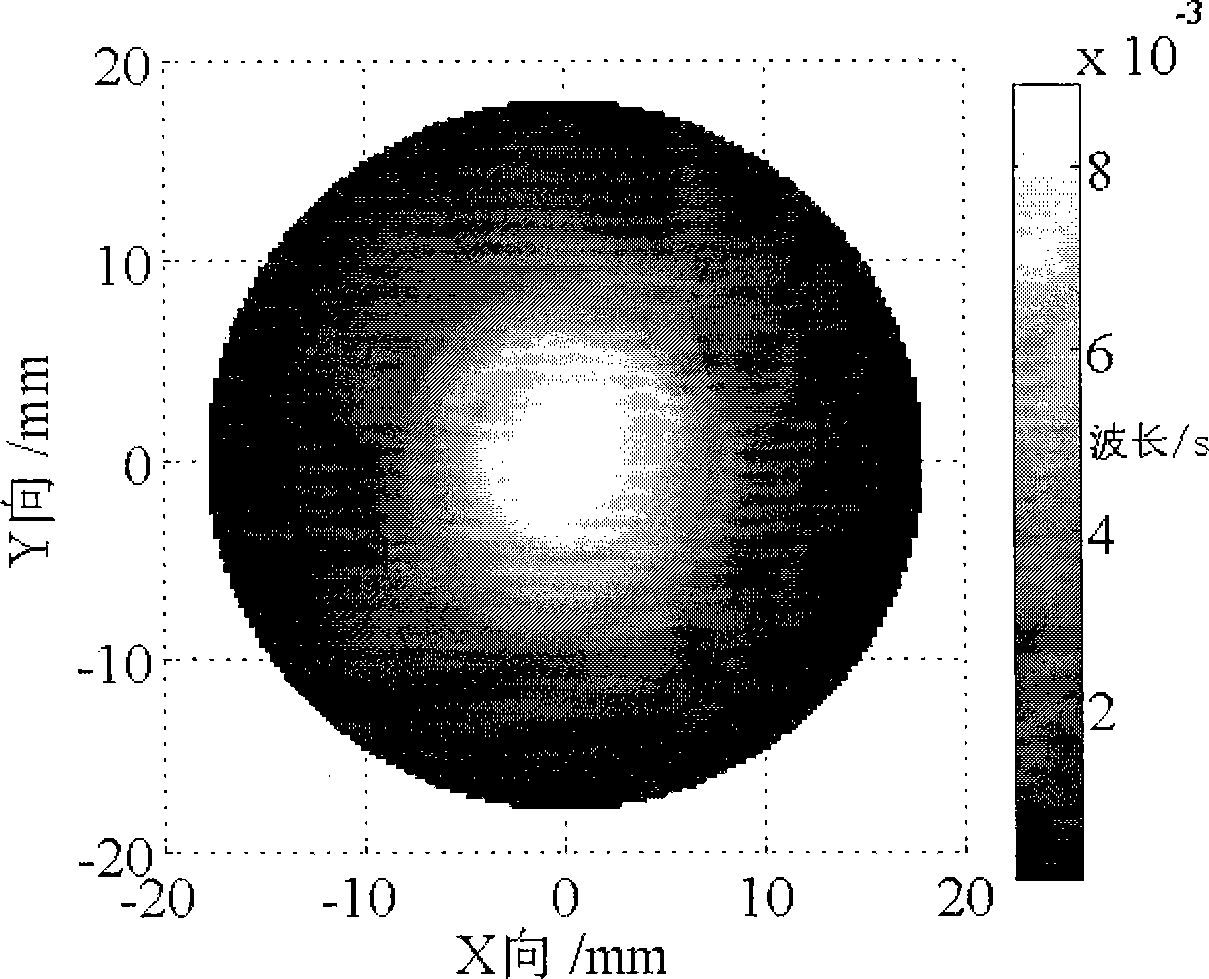
[0040] 1. Determine the removal function: apply the above-mentioned ion beam polishing process to carry out the removal function test, and the obtained removal function is recorded as R c (x, y), which is distributed as figure 2 shown;

[0041] 2. Rotational symmetry processing of the removal function: According to the removal function obtained in step 1, the removal function is searched for the optimal center of rotation and the rotation symmetry processing is carried out. The value of each parameter in the rotat...


PUM

PropertyMeasurementUnit
diameteraaaaaaaaaa

Abstract

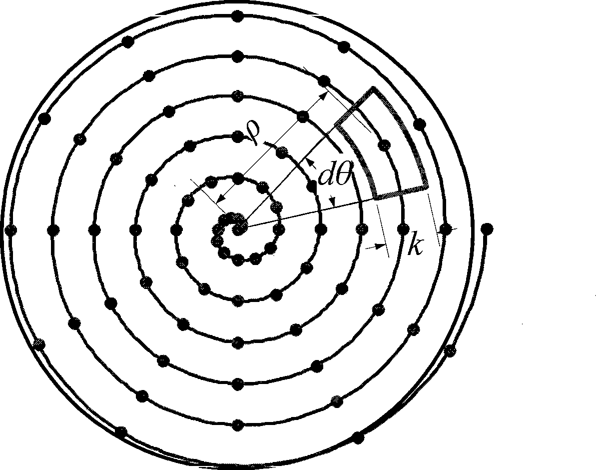
The invention discloses an ion beam polar axis processing method capable of correcting and removing local error of an optical element, which comprises the following steps: firstly acquiring a removal function through experiment, then carrying out rotary symmetric treatment on the removal function, next using a wave surface interferometer to acquire a surface shape error function of the element, establishing a shaped model and calculating density distribution of residence time, solving the residence time in an Archimedes path, then adjusting screw pitch according to circumstances, and generating a numerical control code according to sector Archimedes spiral discrete information and synthesized motion speed of each discrete sector area to carry out first numerical control shape-correcting processing, and finally repeating the processing steps more than once according to the circumstances till meeting the accuracy requirement of a work piece. The processing method reduces requirement of the mirror surface size on processing system size, saves processing cost, overcomes the defect that the prior polar axis processing mode can not carry out error correction on non-rotary symmetry error of the mirror surface, and ensures processing efficiency.

Description

technical field [0001] The invention belongs to the field of ion beam processing of optical elements, in particular to an ion beam polar axis processing method of optical elements. Background technique [0002] The optical mirror ion beam processing method uses the ion sputtering effect to remove materials from the atomic scale, uses a near-Gaussian beam to enter the workpiece to form a removal function with a near-Gaussian distribution, and then deterministically corrects the mirror error based on the principle of optical mirror shaping (CCOS). Features such as high precision, high determinism, non-contact, no wear and no edge effect. However, the principle of material removal in ion beam processing determines that the entire processing process must be completed in a vacuum environment, which determines that the construction of the ion beam processing system is complex and the cost of use and maintenance is high. [0003] The ion beam processing method generally adopts the...

Claims


Application Information

Patent Timeline
Patent Type & Authority Applications(China)
IPC IPC(8): C03C23/00
Inventor 解旭辉李圣怡戴一帆焦长君周林郑子文谷文华
Owner NAT UNIV OF DEFENSE TECH
Learn More