Industrial waste gas combustion apparatus and method

A technology of industrial waste gas and combustion device, applied in the direction of combustion method, combustion type, combustion equipment, etc., can solve the problems of insufficient mixing of gas and combustion-supporting gas, unsuitable for industrial waste gas combustion, etc., achieves low resistance, reduced length, and increased full capacity degree of effect

Inactive Publication Date: 2009-06-17
刘武标
View PDF3 Cites 10 Cited by
  • Summary
  • Abstract
  • Description
  • Claims
  • Application Information

AI Technical Summary

Problems solved by technology

This multi-purpose burner can burn various fuels such as heavy oil, natural gas, city gas, etc. However, when this burner burns natural gas or city gas, the gas and combustion-supporting gas cannot be fully mixed, and it is not suitable for the combustion of industrial waste gas.

Method used


Image

  • Industrial waste gas combustion apparatus and method
  • Industrial waste gas combustion apparatus and method

Examples


Embodiment 1

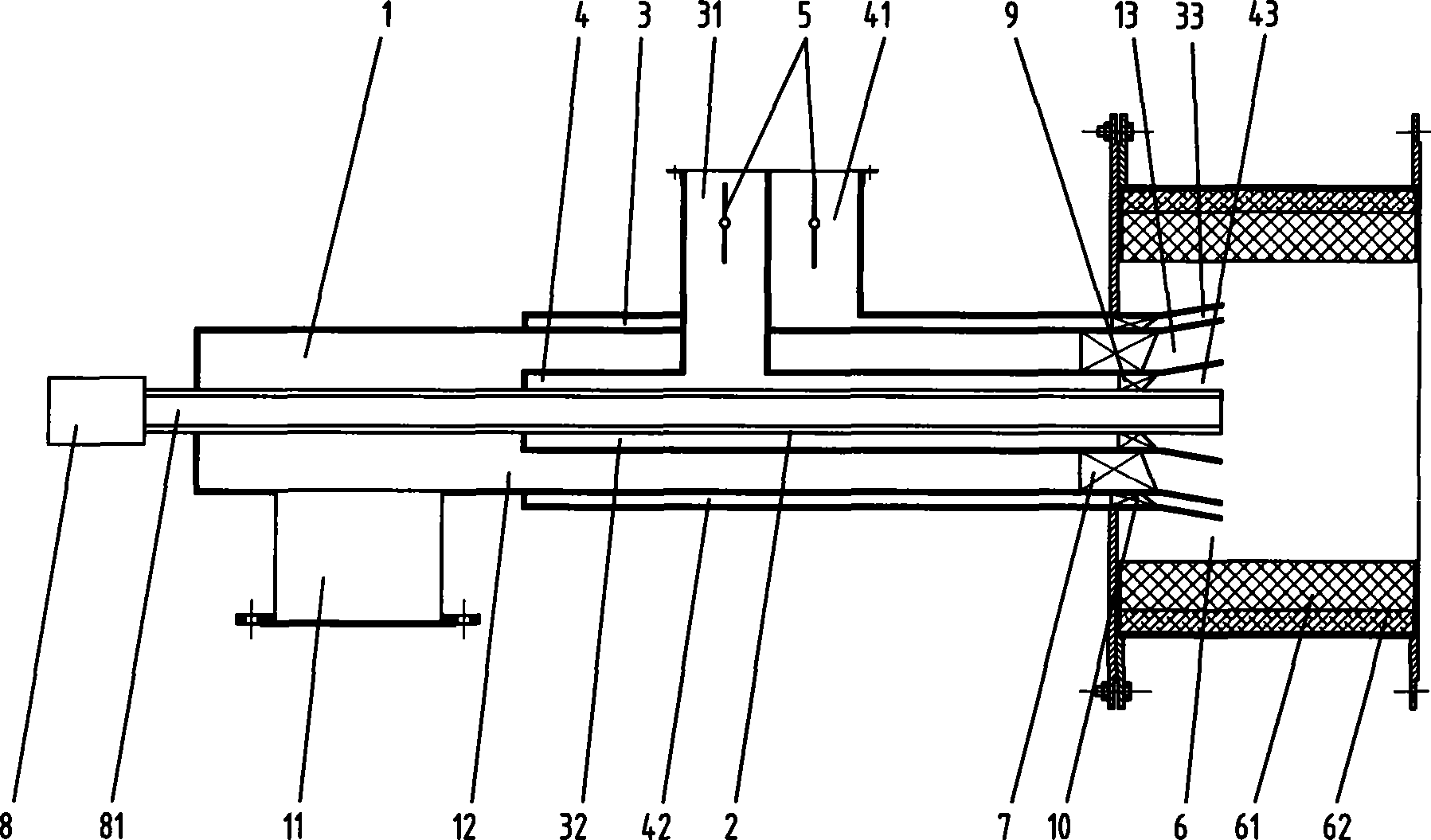
[0029] Please refer to figure 1 , The industrial waste gas combustion device of the present invention includes an industrial waste gas channel 1, an ignition gun tube 2, a primary air channel 3, a secondary air channel 4, and a combustion stabilization chamber 6 that is poured with refractory cement 61 and thermal insulation cotton 62.

[0030] The industrial exhaust gas channel 1 includes an air intake pipe 11, a cylindrical annular channel 12 and a horn-shaped annular channel 13. The role of the horn-shaped annular channel 13 is to increase the fullness of the flame produced by the burner on the one hand, and to reduce the fullness of the flame on the other hand. length. Ten spoiler vanes 7 are installed at the tail of the cylindrical annular channel 12 of the industrial waste gas channel 1 .

[0031] The ignition gun barrel 2 is used for installing the electronic ignition gun 81 in the ignition device 8 .

[0032] The primary air channel 3 includes a square inlet section ...

Embodiment 2

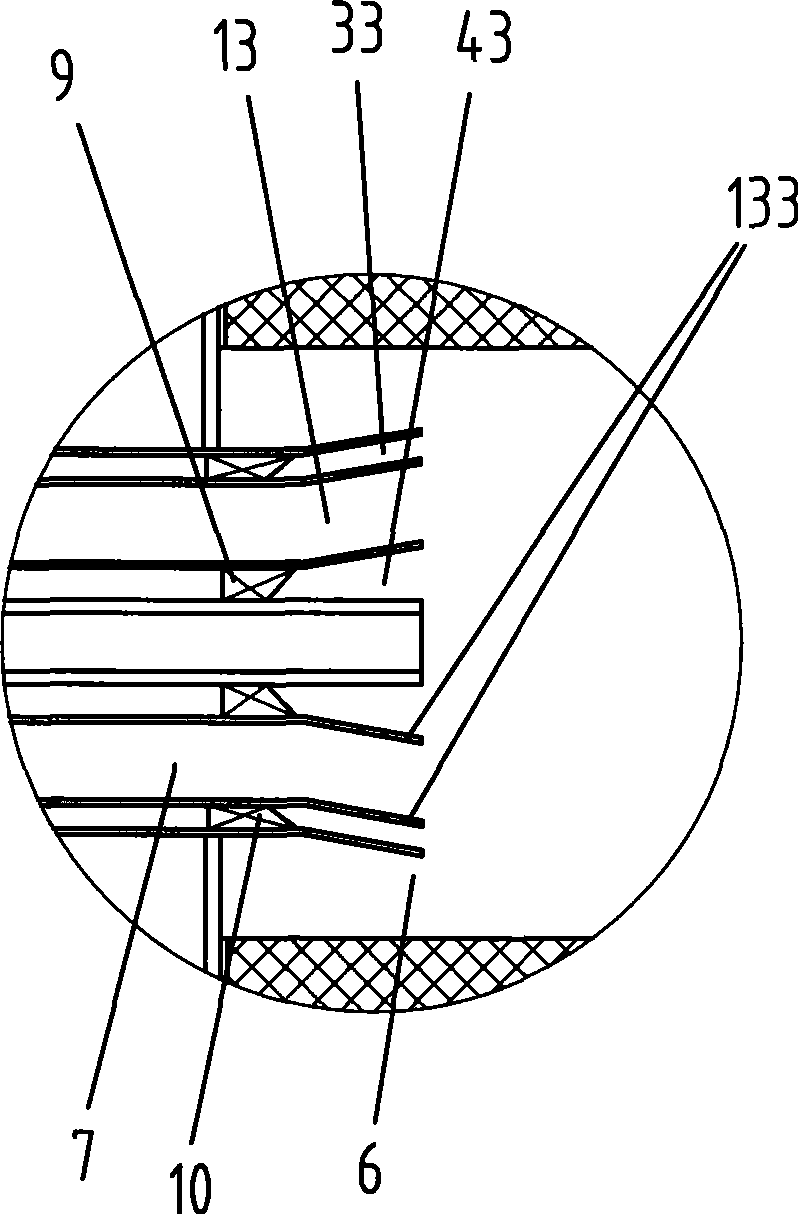
[0039] Please refer to figure 2 , as another kind of scheme of the present invention, other parts are identical with embodiment 1, and difference is:

[0040] Spoiler blades 7 are not installed at the tail of the cylindrical annular passage 12 of the industrial waste gas passage 1, and thirty small holes 133 are opened in the trumpet-shaped annular passage 13 of the industrial waste gas passage 1. The diameter of the small hole 133 is 2mm, 3mm or 4mm.

[0041] When in use, the primary air velocity in the primary air channel 3 is controlled at 55m / s; the secondary air velocity in the secondary air channel 4 is controlled at 30m / s; the industrial exhaust gas velocity in the industrial exhaust channel 1 is controlled at 25m / s.

Embodiment 3

[0043] As another kind of scheme of the present invention, other parts are identical with embodiment 1, and difference is:

[0044] The primary air channel 3 and the secondary air channel 4 are not provided with spoiler blades. Also, the stabilizing chamber 6 is not used.

[0045] When in use, the primary air velocity in the primary air channel 3 is controlled at 50m / s; the secondary air velocity in the secondary air channel 4 is controlled at 25m / s; the industrial exhaust gas velocity in the industrial exhaust channel 1 is controlled at 15m / s.


PUM


Abstract

The invention discloses an industrial waste gas combustion device and a method thereof. The invention comprises an industrial waste gas channel, at least one primary air channel, and at least one ignition device which is arranged at the terminal end of the industrial waste gas combustion device by extension, wherein, the industrial waste gas combustion device further comprises at least one secondary air channel; the industrial waste gas channel, the primary air channel and the secondary air channel are all ring-shaped channels; the industrial waste gas channel is arranged at the outer side of the primary air channel in a rotating way; and the secondary air channel is arranged at the outer side of the industrial waste gas channel in a rotating way. As the invention uses a structure that the industrial waste gas channel, the primary air channel and the secondary air channel are mutually separated, the combustion is safe and reliable; as a trumpet-shaped ring-shaped channel is used by each channel, the fullness of the flame can be enhanced, the length of the flame can be reduced, and the combustion efficiency can be improved.

Description

technical field [0001] The invention relates to a waste heat recovery device and method, in particular to a waste heat recovery device and method of industrial waste gas. Background technique [0002] The industrial waste gas discharged by most chemical enterprises contains combustible gases, such as H 2 , CO, CH 4 etc. These industrial waste gases are directly discharged into the atmosphere, which wastes resources and pollutes the environment. Since the composition of combustible gas in industrial waste gas only accounts for 10-20%, the calorific value of waste gas is not high, about 500-2000Kcal / Nm 3 , and the gas supply pressure is very low, about 0.4 ~ 1.25Kpa, the calorific value of general natural gas is about 8500Kcal / Nm 3 , Ordinary gas burners require an air supply pressure of 10-150Kpa, so this kind of industrial waste gas with low calorific value and air pressure cannot be burned normally and stably by ordinary gas burners. [0003] As disclosed in Chinese Pat...

Claims


Application Information

Patent Timeline
Patent Type & Authority Applications(China)
IPC IPC(8): F23G7/06F23L1/00F23L9/00
Inventor 刘武标
Owner 刘武标
Why Eureka
Try Eureka