Power factor compensation controller

A technology of power factor compensation and compensation control, applied in the direction of reactive power compensation, reactive power adjustment/elimination/compensation, etc., can solve the problems of slow compensation response time, single compensation method performance, and few reactive power compensation control loops, etc., to achieve The effect of improving the compensation response time, high control precision and strong expansion ability

Inactive Publication Date: 2009-06-17
ACREL
View PDF1 Cites 19 Cited by
  • Summary
  • Abstract
  • Description
  • Claims
  • Application Information

AI Technical Summary

Problems solved by technology

Analyzing the same kind of low-voltage reactive power automatic compensation devices that have been produced at home and abroad, most of them have the following deficiencies: incomplete functions, poor precision, low degree of automation, and slow compensation response time
However, it has few reactive power compensation control circuits (only three sets of compensation capacitors), and there are disadvantages such as single compensation method performance, inflexible compensation control and easy to produce overcompensation phenomenon; and lack of man-machine dialogue interface, the industrial single-chip computer data used The acquisition rate is low, the capacity is small, and the data processing cannot be intelligent; the remote communication cannot be realized

Method used


Image

  • Power factor compensation controller
  • Power factor compensation controller
  • Power factor compensation controller

Examples


Embodiment Construction

[0028] The circuit and usage method of the power factor compensation controller of the present invention will be further described below in conjunction with the accompanying drawings and specific embodiments.

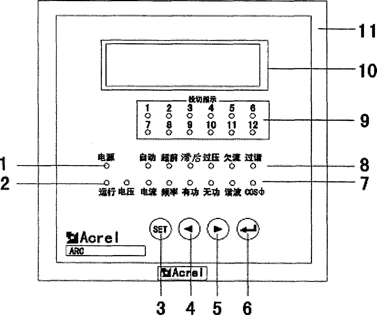
[0029] Such as figure 2 As shown, a power factor compensation controller includes an instrument case 11, an LED display 10 arranged on the front side of the instrument case 11, a power indicator light 1, an operation indicator light 2, 12 groups of switching indicator lights 9, and a display Function indicator light 7, status indicator light 8 and function button 3, down button 4, up button 5, confirm button 6 and the upper, middle and lower rows of connection terminals 4, 5, 6 and setting The circuit board inside the housing 11.

[0030] The power indicator light 1 indicates the working power of the system, the operation indicator light 2 indicates whether the system is running normally, the 12 groups of switching indicator lights 9 indicate the current switching of ...


PUM


Abstract

The invention relates to a power factor compensation controller, wherein a circuit comprises a power circuit, a voltage current sampling circuit, a CPU treatment circuit, an LED display circuit, a compensation control output circuit, a switching value input output circuit and an RS485 communication circuit, wherein an quantitative value, a switching value signal and a temperature signal in a screen are sent to the CPU treatment circuit to be treated, the quantitative value is output after a voltage signal and a current signal are sampled by the voltage current sampling circuit through A/D digital analog conversion, the switching value signal is input by the switching value input output circuit, output voltage, current, frequency, active power, reactive power, active harmonic percentage, power factors and temperature signals are transported to other peripheral equipment through the RS485 communication circuit, the CPU treatment circuit further outputs a fan control signal in an external capacitor box through the switching value input output circuit, and switches external compensation capacitor through the compensation control output circuit. The power factor compensation controller has the functions that the speed rate is high, data can be collected and treated intelligently in large capacity and real time, and the remote communication can be achieved and the like.

Description

technical field [0001] The invention relates to a reactive power compensation device for compensating reactive power in a low-voltage power distribution system. It is especially used in conjunction with various types of electrostatic capacitive screens with voltages below 400V, so that the power factor can be automatically stabilized between 0.9-1. compensation controller. Background technique [0002] With the development of electric power production, the requirements for grid power supply are getting higher and higher, which is mainly reflected in the higher and higher requirements for power distribution measurement accuracy and more and more monitoring indicators. Analyzing the same kind of low-voltage reactive power automatic compensation devices that have been produced at home and abroad, most of them have the following shortcomings: incomplete functions, poor precision, low degree of automation, and slow compensation response time. Chinese utility model patent ZL98223...

Claims


Application Information

Patent Timeline
Patent Type & Authority Applications(China)
IPC IPC(8): H02J3/18
CPCY02E40/30
Inventor 李文权周中
Owner ACREL
Why Eureka
Try Eureka