Debugging apparatus and method based on chirp management laser

A laser and bias current technology, applied in lasers, laser parts, phonon exciters, etc., can solve the problems of low debugging efficiency, complicated debugging, and not suitable for mass production, so as to improve debugging efficiency and simplify debugging procedures. Effect

Inactive Publication Date: 2009-06-24
ZTE CORP
View PDF0 Cites 19 Cited by
  • Summary
  • Abstract
  • Description
  • Claims
  • Application Information

AI Technical Summary

Problems solved by technology

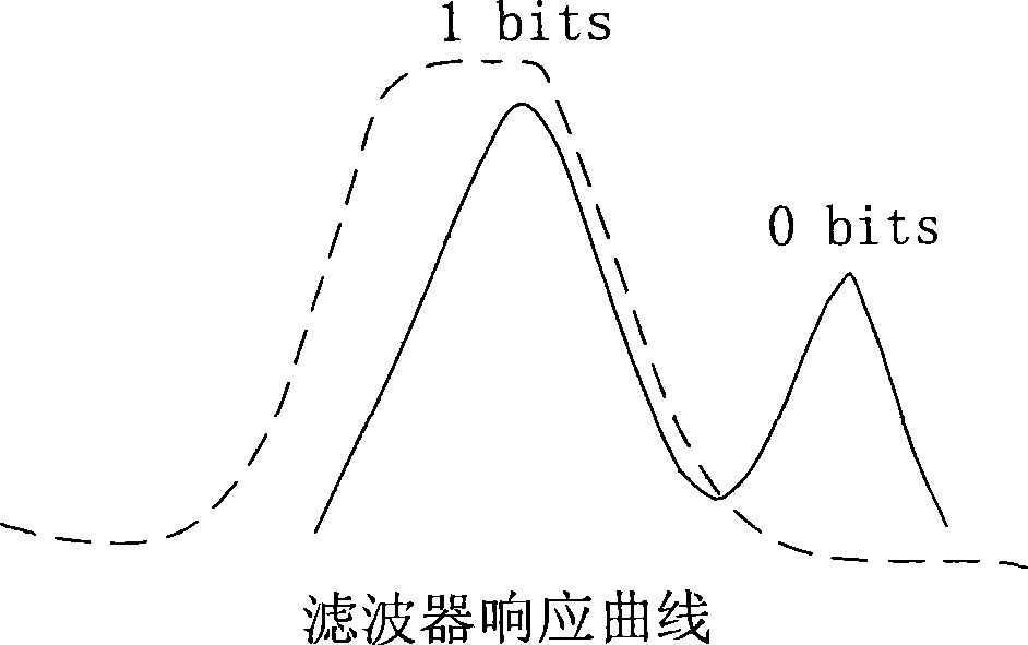
Then, it is also necessary to determine the relative locking position of the central wavelength and the OSR according to the filter loss (Filter Loss). The filter loss refers to the output power when the central wavelength is locked at the center point of the OSR when the laser is not modulated. The output power difference when the signal is locked to the best lock point. At this stage, it is necessary to use the spectrometer to observe the chirp information in the spectrum to select an optimal operating point to achieve the best transmission performance ratio. The debugging is complicated and the debugging efficiency is very low. , not suitable for mass production

Method used


Image

  • Debugging apparatus and method based on chirp management laser
  • Debugging apparatus and method based on chirp management laser
  • Debugging apparatus and method based on chirp management laser

Examples


Embodiment Construction

[0028] The method is a debugging method for quickly and accurately determining the optimal optical signal-to-noise ratio (OSNR) or dispersion of a CML laser-based transmitter in a Dense Wavelength Division Multiplexing (DWDM) system.

[0029] The present invention will be further described in detail below in conjunction with specific embodiments and accompanying drawings.

[0030] See Figure 5 , the debugging device based on chirp management laser of the present invention includes: a laser parameter control unit 100 , a signal sounding unit 200 and a testing unit 300 respectively connected to the CML laser.

[0031] The laser parameter control unit 100 is used to control the commands and the switching unit of the laser, and convert the issued commands into corresponding analog control signals to control the working state of the laser. The laser parameter control unit 100 includes: a radio frequency voltage amplitude control unit 110 , a temperature control unit 120 , a bias ...


PUM


Abstract

The invention discloses a debugging device and a method based on a chirped management laser; the method comprises the following steps: modulation signals produced by an optical domain are converted into electric-domain signals for modulating the laser; the received command signals are converted into simulating control signals for controlling the working state of the laser, and bias current of the laser, tube core temperature and radio-frequency voltage of AC coupling are set according to the simulating control signals; by comparison, if extinction ratio is not in the required range or is not in accordance with the presetting standard of an eye pattern, the temperature of a spectrum shaping element is adjusted. Compared with the prior art by repeatedly debugging according to the loss of the filter, the steps of the method is less, the debugging procedure is obviously simplified, thus improving the debugging efficiency; the debugging device only adopts a radio-frequency voltage amplitude control unit, a temperature control, a bias current control unit and a laser tube core temperature control unit for carrying out debugging, thus simplifying debugging procedure and improving the debugging efficiency.

Description

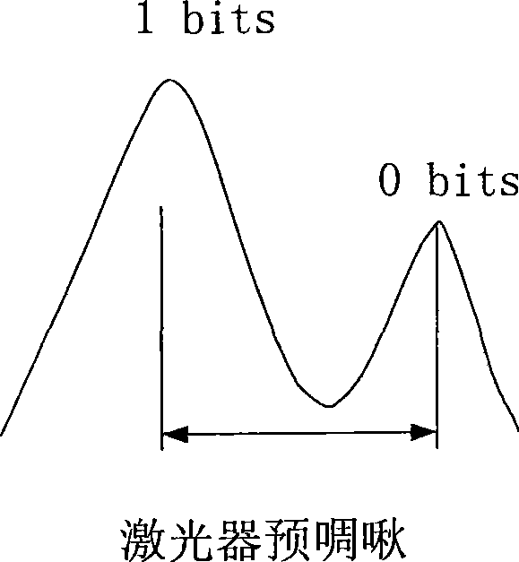
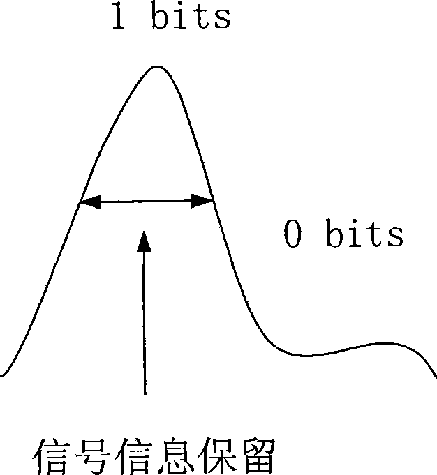
technical field [0001] The invention relates to intensive light wave multiplexing technology, in particular to a debugging device and method for a chirp-based management laser. Background technique [0002] Lasers include directly modulated lasers (directly modulated laser, DML) and electro-absorption modulated lasers (Electro-Absorption Modulated Laser, EML). In the existing 10Gb / s DML laser, a special filter made by Chirp Managed technology is adopted to form a Chirp Managed Laser (CML). The special filter used in the CML laser is actually a spectral shaping element (Optical Spectrum Reshaper, OSR), which is used to process the emission spectrum output by the laser after direct modulation, and filter out the chirp that is not conducive to transmission. . Because when the distributed feedback (Distributed Feed Back, DFB) laser injects a large bias current, the laser enters the saturated light emitting state, and after adding the direct modulation current, the laser adiaba...

Claims


Application Information

Patent Timeline
Patent Type & Authority Applications(China)
IPC IPC(8): H01S3/13
Inventor 崔平
Owner ZTE CORP
Why Eureka
Try Eureka