
Backlight module and production method of its substrate

A technology for a backlight module and a manufacturing method, applied in optics, nonlinear optics, instruments, etc., can solve problems such as lamp blackheads, increased thickness of liquid crystal display devices, etc., achieve manufacturing process and convenience, simplify manufacturing process, and simplify lamp manufacturing. effect of the program

Inactive Publication Date: 2010-12-15
DARFON ELECTRONICS CORP
View PDF5 Cites 0 Cited by
  • Summary
  • Abstract
  • Description
  • Claims
  • Application Information

AI Technical Summary

Problems solved by technology

[0004] However, in the era of ever-changing science and technology, liquid crystal display devices are increasingly emphasizing lightness, thinness and shortness. Although the US2005 / 0017619A1 patent effectively solves the problem of blackheads in the prior art and simplifies the production process of the lamp, it uses phosphor coating and spraying on the The upper or lower surface of the transparent substrate also increases the thickness of the liquid crystal display device

Method used


Image

  • Backlight module and production method of its substrate
  • Backlight module and production method of its substrate
  • Backlight module and production method of its substrate

Examples


Embodiment Construction

[0033] In order to further understand the purpose, structure, features, and functions of the present invention, the detailed description of the accompanying examples is as follows.

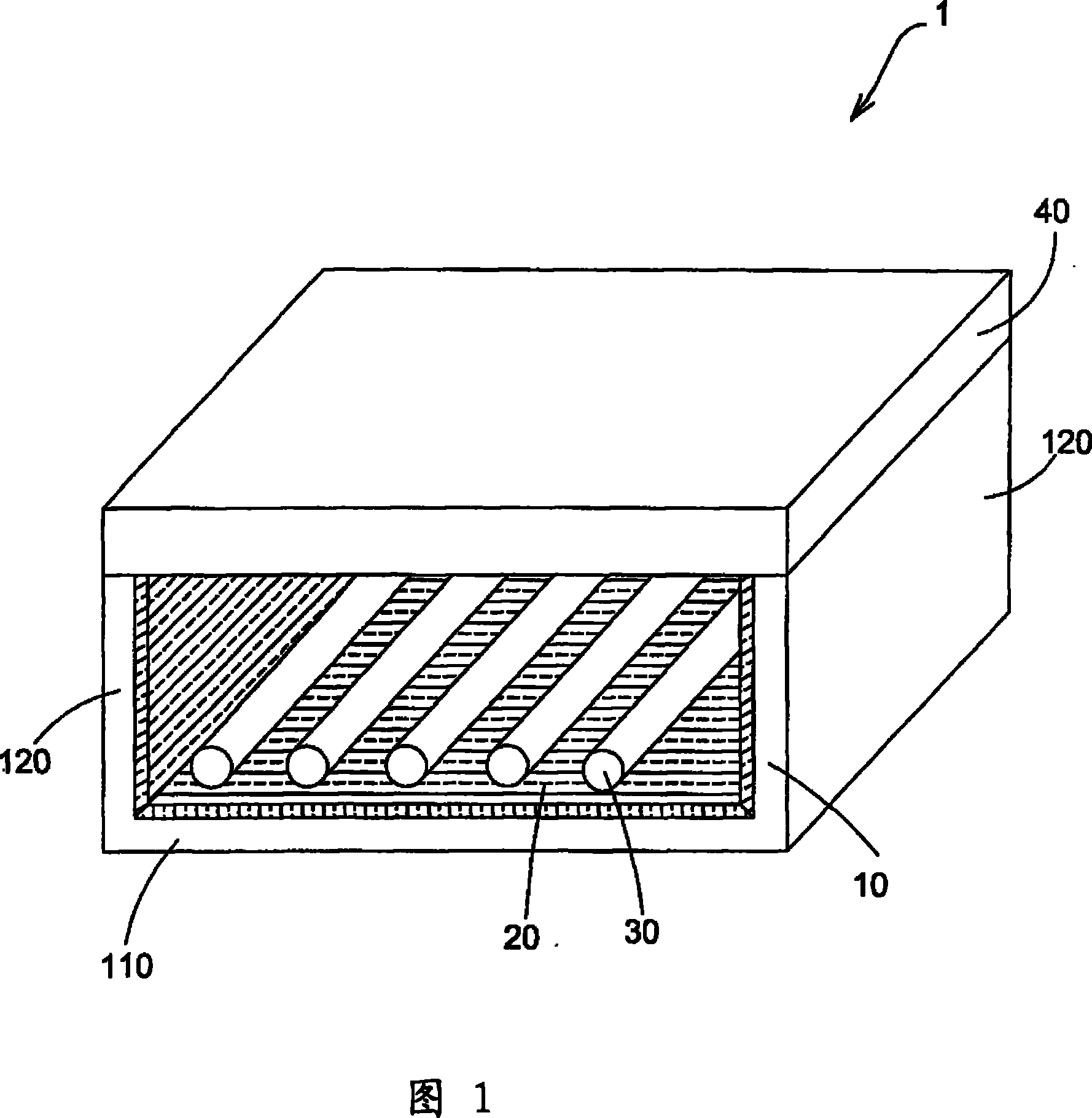
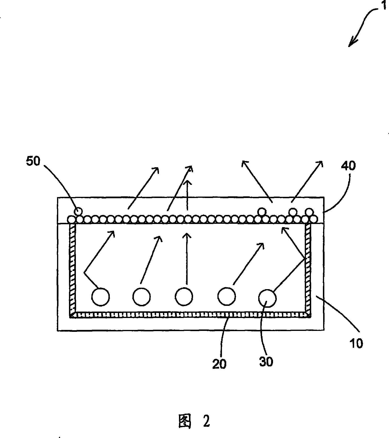
[0034] see figure 1 Shown is a three-dimensional structure diagram of the backlight module 1 of the present invention. As shown in the figure, the backlight module 1 of the present invention consists of a cavity-shaped reflector 10, a reflector 20 disposed on the inner wall of the cavity-shaped reflector 10, a plurality of lamp tubes 30 disposed inside the cavity-shaped reflector 10, and a cavity-shaped reflector. The reflector 10 is composed of a transparent substrate 40 .

[0035] The cavity-shaped reflector 10 is a reflector structure in which three flat plates are arranged in a concave shape. It has a base plate 110 and two side plates 120 perpendicular to the two ends of the base plate 110, for reflecting the light beam of the lamp tube 30 on the liquid crystal panel (not shown in the figure...


PUM

PropertyMeasurementUnit
particle diameteraaaaaaaaaa

Abstract

A backlight module comprises a transparent substrate and at least one light source, wherein the transparent substrate is doped with fluorescent powder, the fluorescent powder is substantially centralized on one side of the transparent substrate, specific weights of the transparent substrate and the fluorescent powder are different, the light source connected to the transparent substrate provides light beams for the transparent substrate and changes color of the light beams via the fluorescent powder. In the backlight module, the manufacturing method of the transparent substrate comprises the following steps: providing a mould, uniformly mixing the transparent plastic and the fluorescent powder and adding a hardening agent to form mixed liquid, the specific weight of the fluorescent powderis larger than that of the transparent plastic, filling the mixed liquid into the mould, and then solidifying the mixed liquid to form a substrate, and finally concentrating the fluorescent powder toone side of the substrate.

Description

technical field [0001] The present invention relates to a manufacturing method of a backlight module and its substrate, in particular to a backlight module and a manufacturing method of the substrate which add fluorescent powder to the substrate and use the fluorescent powder to change the color of light beams. Background technique [0002] The light source used in the backlight module of the liquid crystal display device in the prior art all adopts a cold cathode fluorescent lamp (Cold Cathode Fluorescent Lamp, CCFL), which is coated with fluorescent powder on the inner wall of the lamp tube. When a high voltage is applied to the lamp tube, after the electrons released by the lamp tube electrodes collide with the mercury vapor in the lamp tube, the mercury vapor is excited and becomes an excited state, and when it returns to a stable state, it will release ultraviolet light, and It is absorbed by the fluorescent powder coated on the inner wall of the lamp tube, and then emi...

Claims


Application Information

Patent Timeline
Patent Type & Authority Patents(China)
IPC IPC(8): G02F1/13357C08L33/12C08L69/00C08L67/03C08K11/00
Inventor 黄弘毅
Owner DARFON ELECTRONICS CORP
Learn More