Phase-change radiating device

A heat-dissipating device and phase-change technology, applied in indirect heat exchangers, lighting and heating equipment, lasers, etc., can solve the problems of low heat dissipation efficiency, large volume, and reduced beam quality, and achieve improved heat dissipation efficiency, improved luminous efficiency, Wide range of effects

Inactive Publication Date: 2009-07-01
PHOEBUS VISION OPTO ELECTRONICS TECH +1
View PDF0 Cites 17 Cited by
  • Summary
  • Abstract
  • Description
  • Claims
  • Application Information

AI Technical Summary

Problems solved by technology

[0004] In addition, in semiconductor-pumped lasers, almost all traditional lasers use water to circulate and cool, which inevitably has the disadvantages of bulky water chillers, inaccurate temperature control, and generally only one temperature can be set, high energy consumption, and high noise. question
At present, the heat dissipation of semiconductor lasers generally adopts heat sinks, heat sinks and sheet microchannels, which are separate components, and some of them are welded together. For low-power devices, this heat dissipation method can meet the requirements, but for high-power The heat dissipation effect of the semiconductor laser separated or combined with heat dissipation is not ideal.
[0005] In short, the heat dissipation efficiency of various heat dissipation devices at present is low. For high-power lasers, the operating temperature of the laser cannot be efficiently reduced, and the heat dissipation is not uniform, resulting in a decrease in the luminous efficiency, output power, and beam quality of high-power lasers. , reduced stability, reduced working life
If water circulation cooling and other methods are used, there will be more problems such as large volume and environmental protection

Method used


Image

  • Phase-change radiating device
  • Phase-change radiating device
  • Phase-change radiating device

Examples


Embodiment Construction

[0027] The present invention will be described in detail below in conjunction with the accompanying drawings and embodiments.

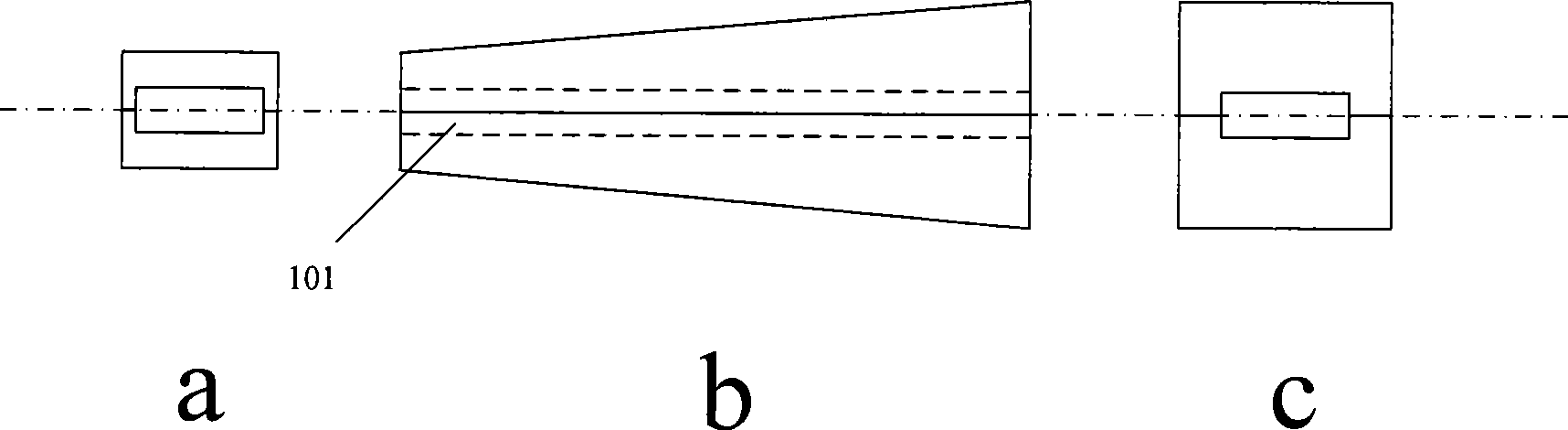
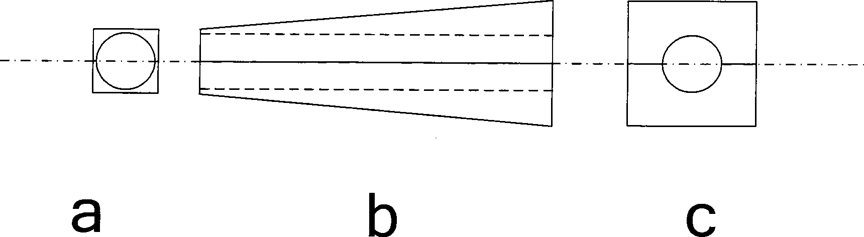
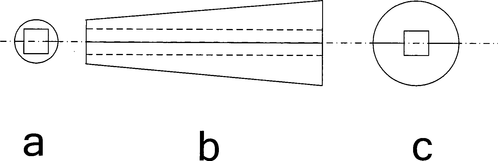
[0028] Figure 1-Figure 4 It is a schematic diagram of four kinds of heat-absorbing component structures in the phase change heat dissipation device.

[0029] Figure 1-Figure 2 It is two kinds of heat-absorbing components of quadrangular truss, whose cross-sections are rectangular and square respectively. image 3 and Figure 4 There are two types of conical heat-absorbing components whose cross-section is circular, such as Figure 1-Figure 4 As shown, the heat-dissipating object 101 is surrounded by heat-absorbing components, which can quickly and effectively conduct the generated heat away, wherein, Figure 1-Figure 3 The objects to be radiated are flakes, rods and blocks, Figure 4 The objects to be dissipated are also block-shaped. Such as figure 1 b- Figure 4 As shown in b, since the side section of the heat-absorbing component is wedge-...


PUM


Abstract

The invention provides a phase-change heat dissipating device and a laser. The phase-change heat dissipating device comprises a vaporizing chamber, a condensation chamber, and a heat conducting end for conducting heat generated by an object to the vaporizing chamber, wherein the heat conducting end comprises a heat absorption assembly covering the object. According to the above technical scheme, the phase-change heat dissipation device has the advantages of simple structure, high heat dissipation efficiency, uniform heat dissipation, high reliability, wide application range, etc., and can be used for dissipating heat of large-power optical components, such as laser crystals, nonlinear optical crystals or semiconductor laser chip of a large-power laser, thereby uniformly dissipating heat, improving the heat dissipation efficiency, effectively improving the light emission efficiency, light output power, beam quality and service life of the large-power laser, and achieving more stable and reliable performance. In addition, the heat dissipating device has relative simple structure, wide application range, environment-friendly energy source and actual value for scale production, and can effectively reduce the size of the large-power laser.

Description

technical field [0001] The invention relates to a heat dissipation device, in particular to a phase change heat dissipation device for a high-power laser. Background technique [0002] High-power semiconductor laser arrays and high-power all-solid-state lasers have become hot pursuits by various countries due to their broad application prospects and huge potential markets. At present, the main problem faced by the high-power semiconductor laser array is the low performance of the laser, that is, the power, efficiency, reliability, stability, and poor consistency of the laser, which largely limits its practical application. The performance of the laser is not only related to the epitaxial material, but also related to the heat dissipation of the laser. Due to factors such as conversion efficiency, the integration of light-emitting devices leads to heat enrichment, which will cause the junction temperature of the active region of the laser to rise, thereby reducing The photoe...

Claims


Application Information

Patent Timeline
Patent Type & Authority Applications(China)
IPC IPC(8): H01S5/024H01S3/042H01L23/427F28D15/02
Inventor 许江珂王斌郑光闵海涛房涛毕勇贾中达
Owner PHOEBUS VISION OPTO ELECTRONICS TECH
Why Eureka
Try Eureka