

Method for manufacturing porous body
A manufacturing method and technology of porous bodies, which are applied in the direction of manufacturing tools, ceramic products, casting equipment, etc., can solve the problems of inability to apply to large-scale and large-scale manufacturing, and achieve the effect of simple manufacturing method, simplified structure, and simplified control principle.
- Summary
- Abstract
- Description
- Claims
- Application Information
AI Technical Summary
Problems solved by technology
Method used
Image

Examples
Embodiment approach 1
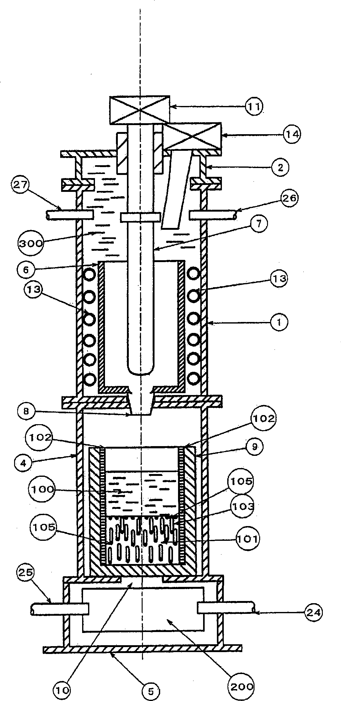
[0144] figure 1 It is a cross-sectional view schematically showing an example of an apparatus for manufacturing the porous body 101 used in the present invention. figure 1 The shown apparatus is provided with a heating unit container 1 for heating and melting a raw material for forming a porous body, a solidification adjustment unit container 4 for cooling and solidifying a molten raw material 100 , and a cooling unit container 5 arranged vertically. The heating unit container 1 includes a crucible 6 , a crucible stopper rod 7 , an induction heating coil 13 , a gas injection port 26 , a gas discharge port 27 , and a funnel 8 . Further, a driving unit 11 for pulling up the container lid 2 and the crucible closing rod 7 is provided on the upper portion of the heating unit container 1 .
[0145] First, the crucible stopper rod 7 is lowered to the closed position, and after filling the crucible 6 with raw materials, the container lid 2 is closed, and the inside is depressurized u...
Embodiment approach 2
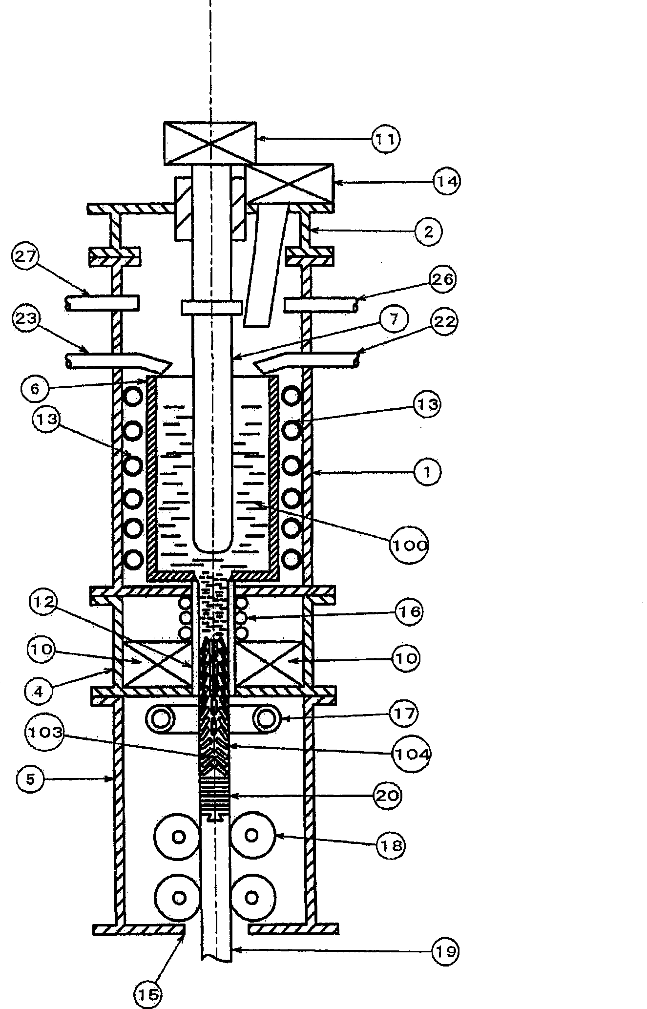
[0150] figure 2 It is a figure which schematically shows an example of the vertical apparatus which manufactures the porous continuous body 104 by the continuous casting method. figure 2 In the shown apparatus, a heating vessel 1 for heating and melting a raw material, a solidification control unit vessel 4 , and a cooling unit vessel 5 are installed in the vertical direction. The molten raw material 100 that has passed through the continuous casting mold 12 moves downward while being cooled, and is solidified to form a porous continuous body 104 . In the cooling unit container 5, the auxiliary cooling unit 17 is continuously cooled by the cooling water 200 to increase the temperature gradient, so that the shape of the pores 103 continuously formed in the porous continuum 104 is kept consistent in the same direction, And pull out the porous continuum 104 downward.
[0151] The raw material that has been subjected to degassing treatment is loaded in advance in the raw mater...
Embodiment approach 3
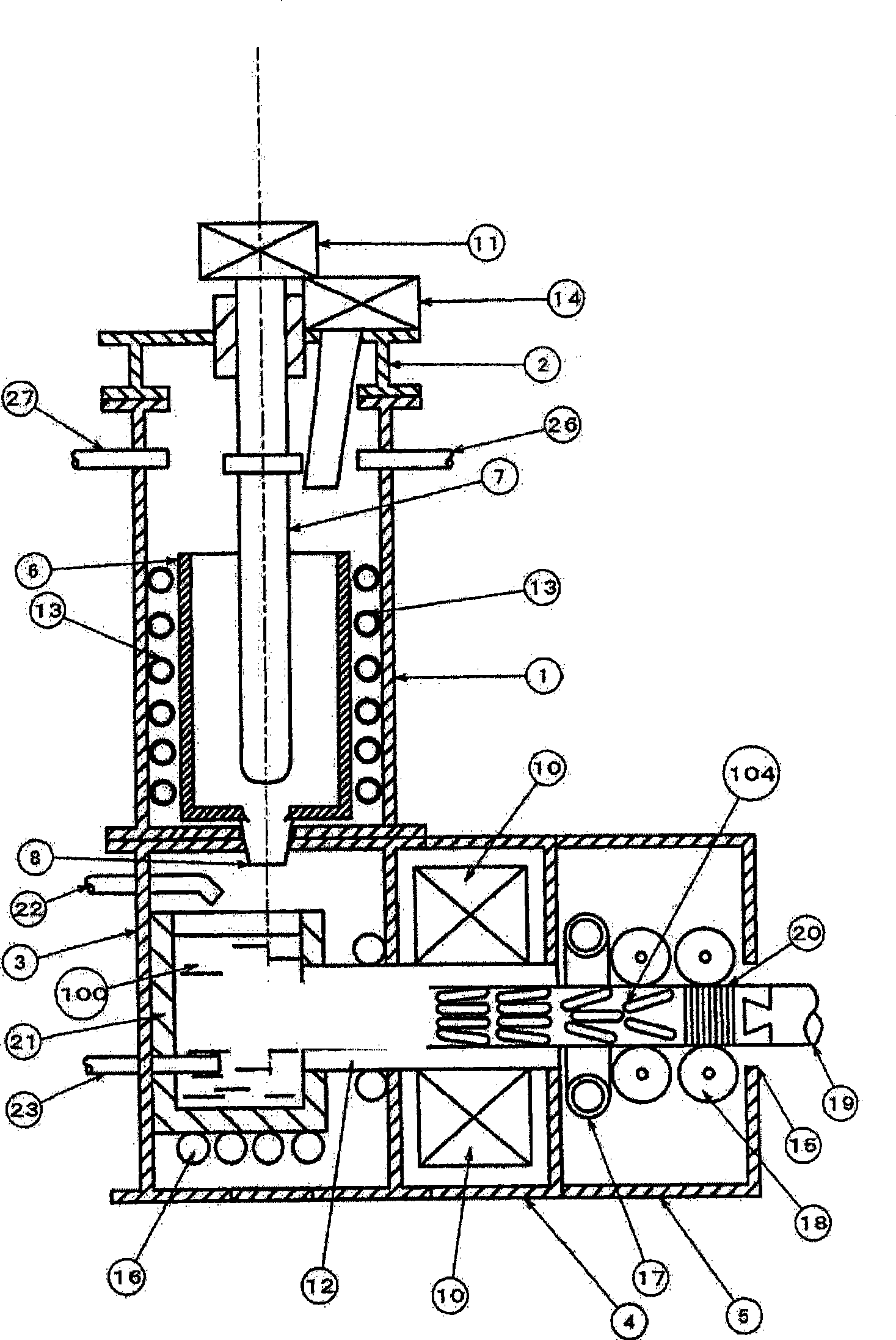
[0154] image 3 It is a figure which schematically shows an example of the horizontal apparatus which manufactures the porous continuous body 104 by a continuous casting method, and pulls it out in the horizontal direction. image 3 In the shown apparatus, the heating unit container 1 and the heat preservation unit container 3 are arranged in the vertical direction, and the solidification adjustment unit container 4 and the cooling unit container 5 including the auxiliary cooling unit 17 are arranged in the lateral direction. Heating method and figure 1 and figure 2 The apparatus shown is the same. The gas-generating compound 102 is supplied from the compound supply part 22 to the molten raw material 100 in the thermal insulation container 21 provided in the thermal insulation adjustment part container 3 . At this time, the decomposition of the gas-generating compound 102 can be accelerated by passing an inert gas from the stirring part 23 to stir the molten raw material. ...
PUM
| Property | Measurement | Unit |
|---|---|---|
| melting point | aaaaa | aaaaa |
| pore size | aaaaa | aaaaa |
| pore size | aaaaa | aaaaa |
Abstract
Description
Claims
Application Information