
Five-shaft linkage numerical control machining center

A machining center and five-axis linkage technology, which is applied in metal processing equipment, metal processing machinery parts, manufacturing tools, etc., can solve problems such as large X-axis load, reduced precision of parts, and increased error in the shape or size of cutting workpieces. Large acceleration, increased processing speed, and increased stress-bearing area

Inactive Publication Date: 2009-07-15
三六零安全科技股份有限公司 +2
View PDF9 Cites 89 Cited by
  • Summary
  • Abstract
  • Description
  • Claims
  • Application Information

AI Technical Summary

Problems solved by technology

[0002] In the existing technology, there are many types of CNC machining centers, but there are still many shortcomings. Generally, they are suitable for machining shaft parts and box parts, but not suitable for impeller parts.
Moreover, most of them occupy a large area and the utilization rate of machine tools is not high
[0003] (1) From the analysis of the main structure of the CNC machining center, there are many types of traditional gantry structures. The workbench is the X-axis, which moves back and forth under the gantry frame. The size and weight of the workbench and the workpiece are large. The disadvantage of this type of structure is that the machine tool occupies a large area, the X-axis load is large, it is difficult to achieve high-speed movement, and the rigidity of the gantry is relatively poor
Another type of gantry structure, not only the beam moves, but also the column moves with the model. Generally, two screws and two drive motors are required under the X-axis, but when the screw is driven, the screw nut will exert torque on the screw. In addition, if the length of the lead screw is too long, it will cause shaking, which will affect the shape and dimensional accuracy of the cutting workpiece, and when it is used for a long time or contaminated by foreign matter, the pitch and straightness of the lead screw will be affected by wear and tear, and there will be considerable error backlash The increase of the value will cause the increase of the shape or size error of the cutting workpiece, the cost is high, and the rigidity and stability are not easy to guarantee; at the same time, due to the high gantry frame, the movement speed is difficult to increase, and the cutting force is relatively small, so that the impact of vibration on the machine tool is small. larger
[0004] (2) The traditional CNC turntable is mostly driven by a worm gear through a servo motor. The worm gear transmission has precision but no power, power but no precision, and the backlash cannot be overcome
Mainly manifested in: ① Due to the large gap in the transmission chain and the friction of the worm gear, the wear is relatively large, which greatly affects the rotation speed and transmission accuracy
②The transmission efficiency of worm gear is low, and the rotation speed is greatly limited, usually below 3000rpm
③ Due to the long transmission path of worm gear transmission, the elastic deformation will also affect the transmission accuracy
When the degree is slight, the vibration is large, the noise is large, the precision of the parts is reduced, and the surface is rough; in severe cases, the system will still make mistakes, and the frequency of failures is high. Because of asynchronous wear and uneven thermal deformation, failures occur every time will appear repeatedly, which brings many difficulties to practical application

Method used


Image

  • Five-shaft linkage numerical control machining center
  • Five-shaft linkage numerical control machining center
  • Five-shaft linkage numerical control machining center

Examples


Embodiment

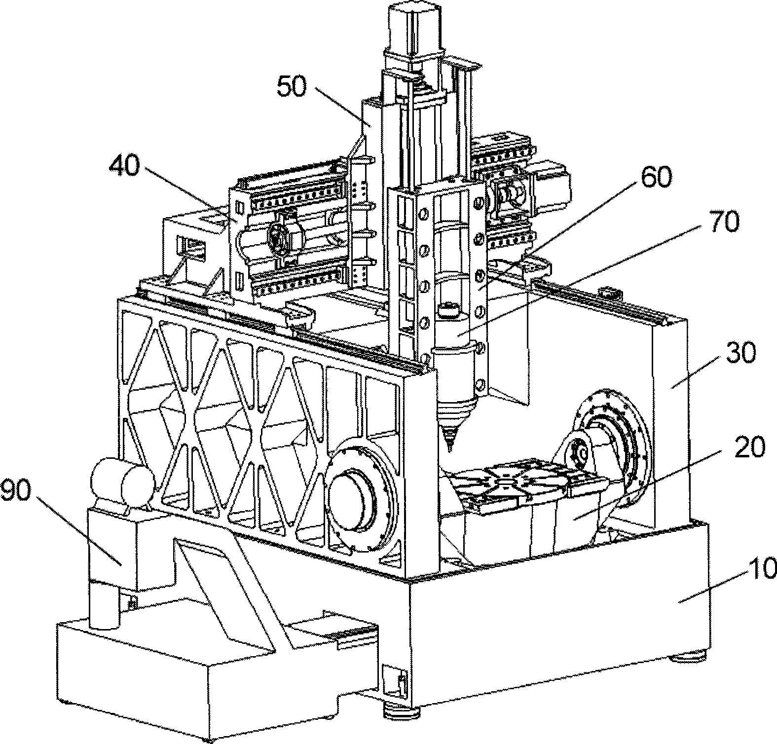
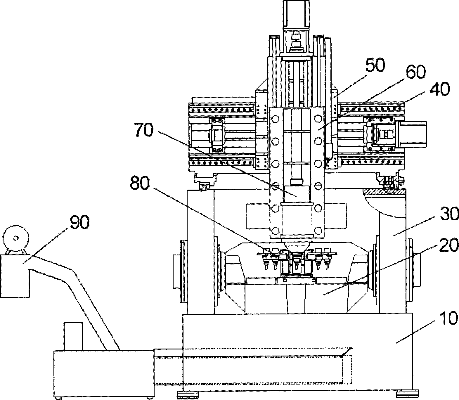
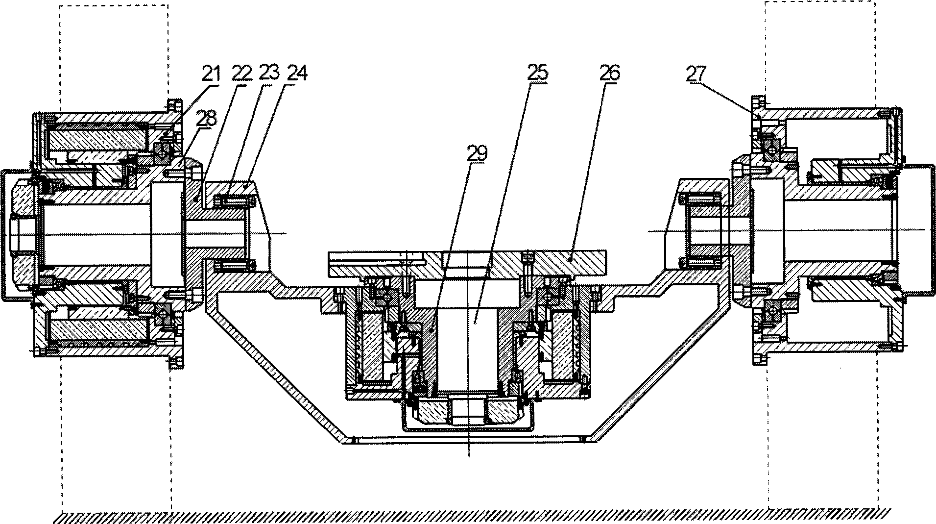
[0033] Example: such as figure 1 , figure 2As shown, a five-axis linkage CNC machining center includes a bed 10 and a gantry frame 30 fixed above the bed 10. The gantry frame 30 includes two left and right gantry columns 32, and is arranged on the two gantry columns. There are 32 fixed gantry beams 35, and the front part of the gantry column 32 is equipped with a direct-drive double-axis precision turntable 20 that can make the workbench 26 rotate around the A and C axes at the same time; the gantry frame 30 is provided with a beam that can move in the Y direction 40. The front part of the beam 40 is provided with a slide plate 50 which can move in the X direction, and the front part of the slide plate 50 is provided with a spindle box 60 which can move in the Z direction. The spindle box 60 is provided with a spindle installation hole 66 for installing the spindle 70; A tool magazine 80 is provided in the cavity between the body 10 and the gantry 30 .

[0034] Such as Fi...


PUM


Abstract

The invention discloses a five-axle linkage digital-control processing centre which comprises a lathe bed (10) and a portal frame (30), wherein the portal frame (30) comprises a left portal upright post (32), a right portal upright post (32) and a fixing portal crossbeam (35), and the front part of each portal upright post (32) is provided with a direct driving type double-shaft precise rotating table (20) which enables a working table (26) to simultaneously rotate round an A shaft and a C shaft. Furthermore, the portal frame (30) is provided with a crossbeam (40) which can move along the Y direction, the front part of the crossbeam (40) is provided with a slide carriage (50) which can move along the X direction, the front part of the slide carriage (50) is provided with a main shaft box (60) which can move along the Z direction, the main shaft box (60) is provided with a main shaft installing hole (66) used for installing a main shaft (70), and a tool magazine (80) is arranged in a cavity positioned between the lathe bed (10) and the portal frame (30). The invention has novel structure, small occupied area, space saving, low cost and stable operation and property. Besides, a motion shaft of a machine tool has high dynamic property, regulating property, positioning precision and repeated positioning precision.

Description

technical field [0001] The invention relates to the technical field of numerical control machine tools, in particular to a five-axis linkage numerical control machining center. Background technique [0002] In the prior art, there are already many types of CNC machining centers, but there are still many shortcomings. They are generally suitable for machining shaft parts and box parts, but not suitable for impeller parts. Moreover, most of them occupy a large area and the utilization rate of machine tools is not high. [0003] (1) From the analysis of the main structure of the CNC machining center, there are many types of traditional gantry structures. The workbench is the X-axis, which moves back and forth under the gantry frame. The size and weight of the workbench and the workpiece are large. The disadvantage of this type of structure is that the machine tool occupies a large area, the X-axis load is large, it is difficult to achieve high-speed movement, and the rigidity ...

Claims


Application Information

Patent Timeline
Patent Type & Authority Applications(China)
IPC IPC(8): B23Q1/01B23Q1/25B23B19/02B23B21/00B23Q3/157
CPCB23Q3/15766B23Q1/012B23Q1/015B23Q1/5437
Inventor 周宏志周明王锐刚余华王康赵万华卢秉恒
Owner 三六零安全科技股份有限公司
Learn More