Low noise amplifier using multipath noise counteraction

A low-noise amplifier and noise cancellation technology, which is applied in the field of low-noise amplifiers and low-noise amplifier circuits, can solve the problems of large noise contribution, non-negligible, high cost, etc., and achieve the goal of reducing circuit noise figure, increasing voltage gain, and offsetting noise contribution Effect

Inactive Publication Date: 2009-07-15
SHANGHAI RUIXIE MICROELECTRONICS TECH
View PDF0 Cites 27 Cited by
  • Summary
  • Abstract
  • Description
  • Claims
  • Application Information

AI Technical Summary

Problems solved by technology

[0007] 1. The noise contribution of the source DC bias part 101 and the load part 103 is usually very large and cannot be ignored, which leads to the fact that the actual noise figure of the circuit is usually much greater than the theoretical minimum value;
[0008] 2. When the circuit is used in a narrowband radio frequency receiver system, the source DC bias part 101 and the load part 103 usually need to use on-chip spiral inductors to obtain better performance, which will increase the design difficulty and chip area, and the cost will be higher. High; and when the circuit is applied to a wideband radio frequency receiver system, parts 101 and 103 can only use resistors or transistor active devices, which contribute a lot to the noise of the whole circuit, and the performance is often difficult to meet the actual application requirements

Method used


Image

  • Low noise amplifier using multipath noise counteraction
  • Low noise amplifier using multipath noise counteraction
  • Low noise amplifier using multipath noise counteraction

Examples


Embodiment Construction

[0028] The present invention is further specifically described below in conjunction with the accompanying drawings.

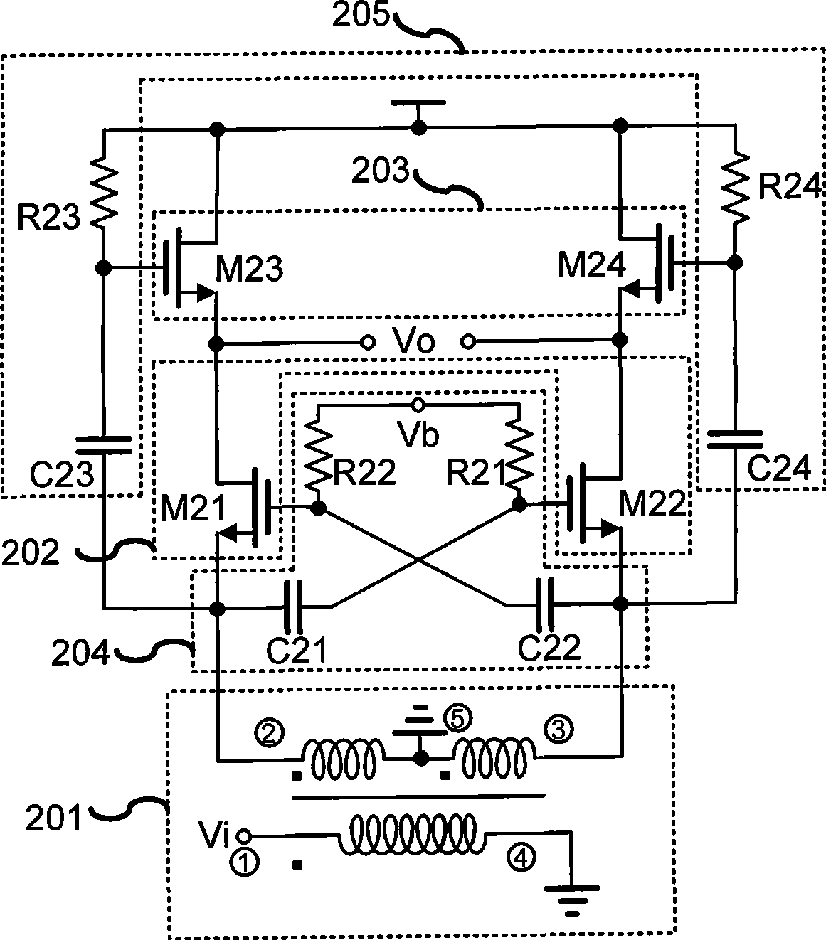
[0029] figure 2 Shown is the specific circuit diagram of the present invention. The picture includes:

[0030] The balanced and unbalanced transformer 201 may adopt an off-chip discrete component or an on-chip integration method. Its first terminal (single-ended) is connected to the signal source, its second terminal and third terminal (two balanced terminals) are respectively connected to the sources of input transistors M21 and M22, and its fourth and fifth terminals are grounded.

[0031] The two balanced ends of the balanced unbalanced transformer 201 are connected to the input transistor in direct current, thereby providing a direct current path for the input transistor without consuming a direct current voltage drop, and no additional bias devices (resistors, inductors or MOS tube current Mirror) provides DC bias for the input transistors, while elimi...


PUM


Abstract

The present invention discloses a low noise amplifier circuit adopting multiplex noise counteract, wherein the low noise amplifier includes a DC connected Balanced to Unbalanced transformer (Balun), a pair of cross coupling connected input transistor with source electrode respectively direct connected to two balancing ends of the Balanced to Unbalanced transformer and the grid respectively AC coupled connected to two balancing ends that different with Balanced to Unbalanced transformer; a pair of transistor load with the grid respectively AC coupled connected to two balancing ends of the Balanced to Unbalanced transformer, and two pairs of electric resistance-capacitance (R-C) high-pass filter network forms cross coupling configuration by connecting the input transistor, two pairs of electric resistance-capacitance high-pass filter network AC couples the input signal to grid of the transistor load tube. The main purpose of the present invention is to realize low noise coefficient and high linearity through multiplex noise counteract technology only consuming low power consumption at the same time.

Description

technical field [0001] The invention relates to a low noise amplifier, in particular to a low noise amplifier circuit with low power consumption and high linearity, and belongs to the technical field of radio frequency integrated circuits. Background technique [0002] With the development of wireless communication technology and integrated circuit technology, the research of low noise amplifier has been widely concerned. The low-noise amplifier is an important part of the front-end of the radio frequency integrated circuit receiver. It is mainly used to amplify the weak signal received by the antenna for subsequent module processing. LNAs not only need to have very low noise figure, but also need to have high linearity and consume as little current as possible. Traditional low-noise amplifiers usually use a common-source amplification structure with source inductance feedback. This structure can obtain a lower noise figure, but requires the use of on-chip inductors, which ...

Claims


Application Information

Patent Timeline
Patent Type & Authority Applications(China)
IPC IPC(8): H03F3/45H03F1/26H03F1/02H03F1/32
Inventor 廖友春金黎明袁路唐长文
Owner SHANGHAI RUIXIE MICROELECTRONICS TECH
Why Eureka
Try Eureka