Index gain modulation distance imager

A technology of modulating distance and imager, which is applied in the directions of instruments, electromagnetic wave re-radiation, and utilization of re-radiation, etc. It can solve the problems of long-time exposure, low instantaneous power, and low ability to obtain the distance of high-speed moving targets, so as to shorten the exposure time, The effect of high instantaneous power and strong acquisition ability

Inactive Publication Date: 2009-07-22
HARBIN INST OF TECH
View PDF0 Cites 5 Cited by
  • Summary
  • Abstract
  • Description
  • Claims
  • Application Information

AI Technical Summary

Problems solved by technology

[0003] The purpose of the present invention is to solve the problem of low instantaneous power of the existing device for acquiring the range image of the high-speed moving target and the need for long-time exposure, resulting in low ability to acquire the distance of the high-speed moving target, thereby providing an exponential gain modulation range imager

Method used


Image

  • Index gain modulation distance imager
  • Index gain modulation distance imager
  • Index gain modulation distance imager

Examples


specific Embodiment approach 1

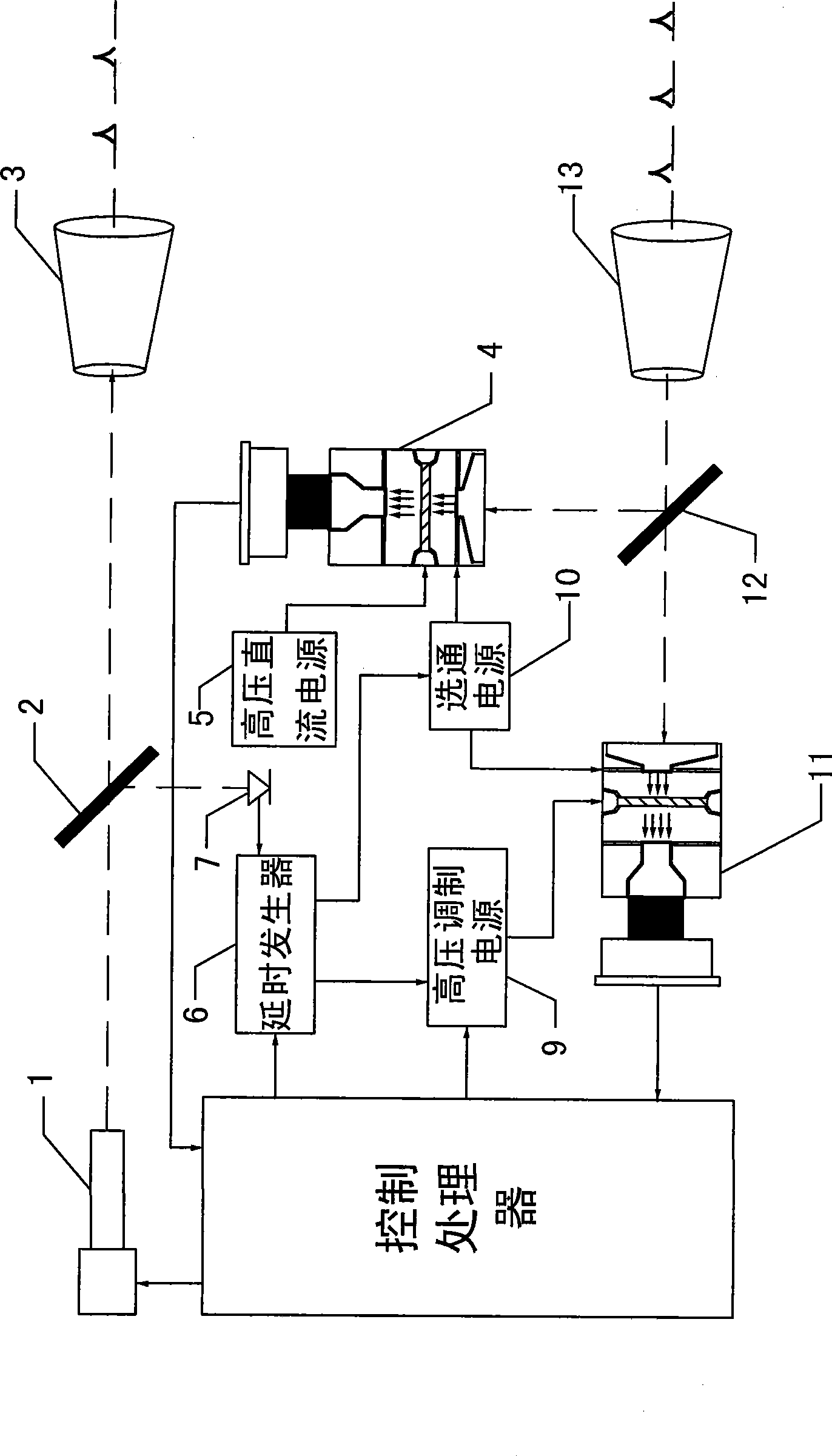
[0007] Embodiment 1: Combining figure 1 Illustrate this specific embodiment, exponential gain modulation distance imager, it is by pulsed laser 1, the first light splitter 2, launch optical shaping system 3, high-voltage DC power supply 5, delay generator 6, photodetector 7, control processor 8. Composed of a high-voltage modulation power supply 9, a gate power supply 10, a first ICCD imager 11, a second ICCD imager 4, a second beam splitter 12 and a receiving optical system 13, the beam output by the pulse laser 1 passes through the first beam splitter 2 Divided into the first reflected light and the first transmitted light, the first reflected light is incident on the light-sensing end of the photodetector 7, the first transmitted light is incident on the input end of the emission optical shaping system 3, and is emitted by the emission optical shaping system 3 The end transmits to the receiving end of the receiving optical system 13, and the output end of the receiving opti...

specific Embodiment approach 2

[0009] Embodiment 2: The difference between this embodiment and the exponential gain modulation range imager described in Embodiment 1 is that the pulsed laser 1 has a power of 1KW-100MW, a line width of 0.01nm-10nm, and a pulse width of 1ns-1000ns of pulsed lasers.

specific Embodiment approach 3

[0010] Embodiment 3: The difference between this embodiment and the exponential gain modulation range imager described in Embodiment 1 or Embodiment 2 is that the voltage range of the high-voltage DC power supply 5 is 500V-1100V.


PUM


Abstract

The invention relates to an index gain modulation distance imager and relates to the field of photoelectronic imaging. The invention solves the problem of poor ability of acquiring distance of a high-speed moving target caused by low momentary power and long time exposure of the existing device for acquiring distance image of the high-speed moving target. In the index gain modulation distance imager, beams output by a pulsing laser are divided into a first reflected light and a first transmitted light by a first light splitting piece; the first reflected light enters the light sensation end of a photoelectric detector; the first transmitted light is divided into two beams by a second light splitting piece after passing through a transmitting optics shaping system and a receiving optics system and the two beams respectively enter the light input terminals of a first ICCD imager and a second ICCD imager. The output terminal of a modulation signal of a high-voltage modulation power source is connected with a microchannel plate of the first ICCD imager and the output terminal of a current signal of a high-voltage direct current power source is connected with a microchannel plate of the second ICCD imager. The imager can be applied to the fields of remote active remote sensing technology, target recognition technology and robot vision technology, etc.

Description

technical field [0001] The invention relates to the field of photoelectric imaging. Background technique [0002] At present, a major problem in the field of optoelectronic imaging is how to obtain the range image of high-speed moving targets. The Scanless Range Imager (SRI) developed by Sandia Laboratories in the United States is currently the range imager with the best lateral resolution and range resolution. It adopts the sinusoidal modulation of the laser and ICCD, and mixes the echo with the gain of ICCD to obtain the phase difference between the two, so as to obtain the distance information of the target. However, because this method uses continuous wave illumination, the instantaneous power is low, and long-time exposure is required, which limits its ability to obtain the distance of high-speed moving targets. Contents of the invention [0003] The purpose of the present invention is to solve the problem of low instantaneous power and long-term exposure of the exi...

Claims


Application Information

Patent Timeline
Patent Type & Authority Applications(China)
IPC IPC(8): G01S17/89
Inventor 孙秀冬靳辰飞赵远刘丽萍张勇张宇何姜
Owner HARBIN INST OF TECH
Why Eureka
Try Eureka