On-line monitoring system for capacitive equipment dielectric loss angle

A medium loss angle and monitoring system technology, applied in the field of monitoring systems, can solve problems such as long signal transmission distance, bottlenecks in off-site signal acquisition and transmission, inconvenient maintenance and expansion, and reduce the difficulty of construction and system installation costs. Scalability and the effect of flexibility, improved reliability and operational efficiency

Inactive Publication Date: 2009-07-29
巨元智能电气(浙江)有限公司
View PDF0 Cites 53 Cited by
  • Summary
  • Abstract
  • Description
  • Claims
  • Application Information

AI Technical Summary

Problems solved by technology

[0003] 1) A large number of cables need to be laid on site, and the construction volume is large, which makes maintenance and expansion inconvenient;
[0004] 2) Using the wired transmission mode, the signal transmission distance is too long, the analog signal will be attenuated to a certain extent and various electromagnetic interferences in the field cannot be avoided. In addition, the wired transmission mode also brings difficulties to the collection and transmission of remote signals. overcoming the bottleneck;
[0005] 3) When measuring the phase difference of power frequency signals, it is necessary to collect power frequency signals detected between different devices in different places (different places) synchronously. Therefore, accurate synchronization signals are required for acquisition devices in different places. The traditional method is to build a wired The communication network, for example, adopts the 485 bus, and the host computer issues data acquisition instructions, and then each monitoring extension unit starts data acquisition synchronously after receiving the acquisition instructions. This method has poor synchronization, and the small phase difference itself will be submerged in the synchronization error.
For monitoring capacitive equipment, the current sensor plays a key role. There is a certain phase difference betw

Method used


Image

  • On-line monitoring system for capacitive equipment dielectric loss angle
  • On-line monitoring system for capacitive equipment dielectric loss angle
  • On-line monitoring system for capacitive equipment dielectric loss angle

Examples


Embodiment Construction

[0046] Referring to the above-mentioned accompanying drawings, specific embodiments of the present invention will be described in detail.

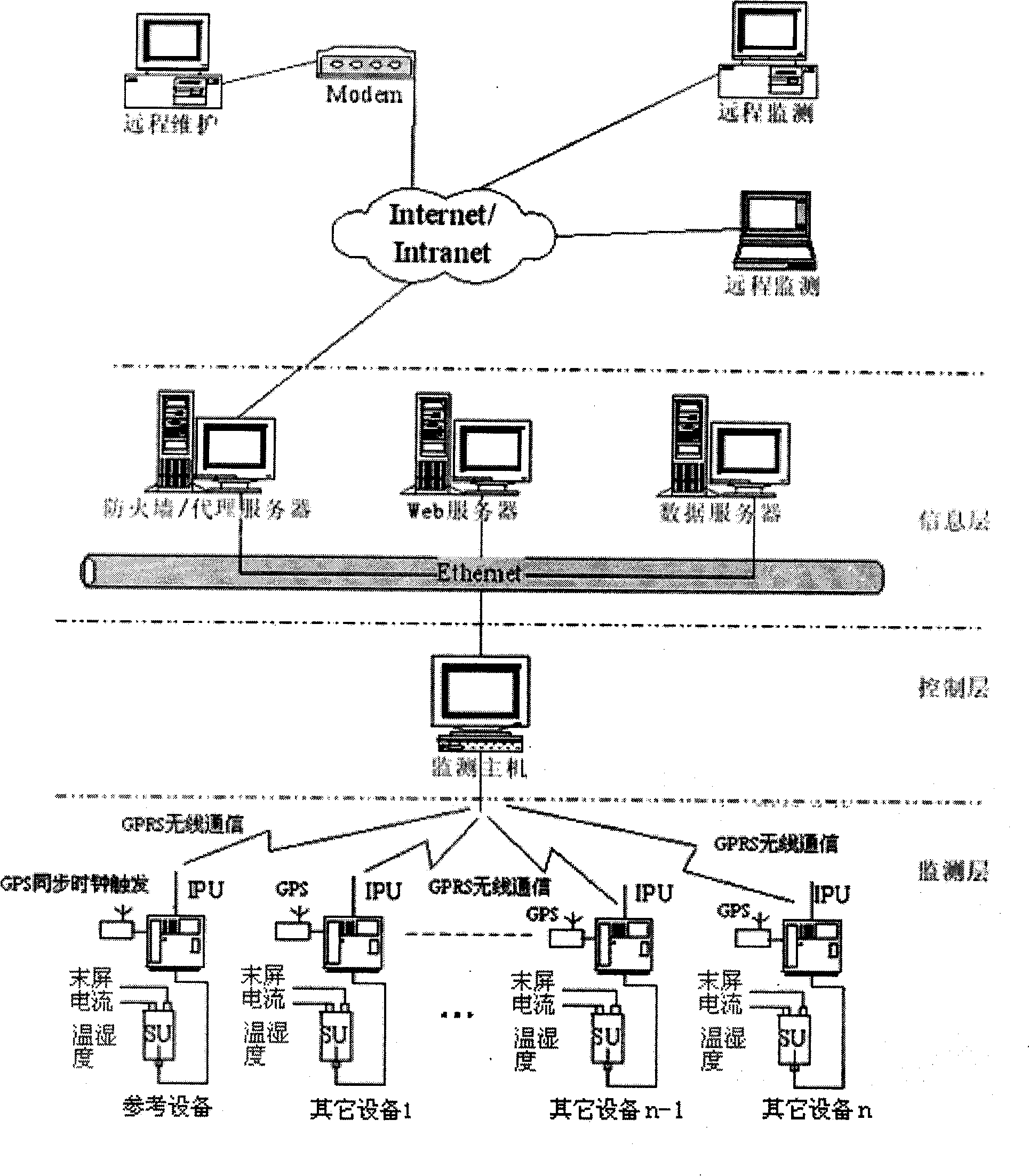
[0047] Such as figure 1 As shown, the whole system is composed of monitoring layer, control layer and information layer. The monitoring layer is mainly realized by the monitoring extension, including two parts: the signal acquisition unit (SU) and the intelligent processing unit (IPU). The SU completes the on-site extraction of the detection signal, and the IPU is mainly composed of the data central processing unit and the A / D sampling module. , GPS module, GPRS wireless communication module and power supply module, among which GPRS can complete the wireless communication with the control layer; the entity of the control layer is the monitoring host, which controls the on-site sampling unit through the GPRS network, reads the data, and then passes the Ethernet The network uploads data to the information layer; the information layer adopts...


PUM


Abstract

The invention relates to a monitoring system for power transmission and transforming equipment, in particular to a capacitive equipment dielectric loss angle online monitoring system. The system is characterized by at least comprising a microprocessor, a leakage current signal acquisition module, a GPS synchronization module, a wireless communication module, an A/D sampling unit, and a frequency measurement sampling unit; in structure, a centralized management mode is used, a wireless data transmission technology and an Internet network technology are applied, and a layered distributed structure is achieved; according to the functional requirements, the invention divides the system into a monitoring layer, a control layer and an information layer. The manufacturer and operating management department (client) can visit the system in different places by only installing browser software and thus easily achieve remote maintenance and monitoring.

Description

technical field [0001] The invention relates to a monitoring system for power transmission and transformation equipment, in particular to an on-line monitoring system for the dielectric loss angle of capacitive equipment. Background technique [0002] Capacitive equipment is an important power transmission and transformation equipment, mainly including current transformers (TA), bushings, coupling capacitors, capacitive voltage transformers (CVT), etc., accounting for about 40% to 50% of the total substation equipment. It occupies an important position in the substation. Its insulation failure not only affects the safe operation of the entire substation, but also endangers the safety of other equipment and personal safety. At present, the maintenance work of power transmission and transformation equipment in my country is mainly to conduct regular preventive tests in accordance with the requirements of the "Electrical Equipment Preventive Test Regulations", that is, regular...

Claims


Application Information

Patent Timeline
IPC IPC(8): G01R27/26
Inventor 黄新波章云刘伟张清玉
Owner 巨元智能电气(浙江)有限公司
Why Eureka
Try Eureka