Microchip for cell alignment and method of cell alignment

A microchip and cell technology, applied in the field of microchips and methods for cell arrangement, can solve the problems of inefficient operation, slow cell transfer, etc., and achieve the effect of accurate operation, fast operation and operation

Inactive Publication Date: 2009-08-05
ABSIZE INC
View PDF3 Cites 4 Cited by
  • Summary
  • Abstract
  • Description
  • Claims
  • Application Information

AI Technical Summary

Problems solved by technology

Further, since cell transfer is slow, although accurate separation can be achieved, it takes a lot of time to separate and extract many cells with optical tweezers, resulting in inefficient operation

Method used


Image

  • Microchip for cell alignment and method of cell alignment
  • Microchip for cell alignment and method of cell alignment
  • Microchip for cell alignment and method of cell alignment

Examples


Embodiment Construction

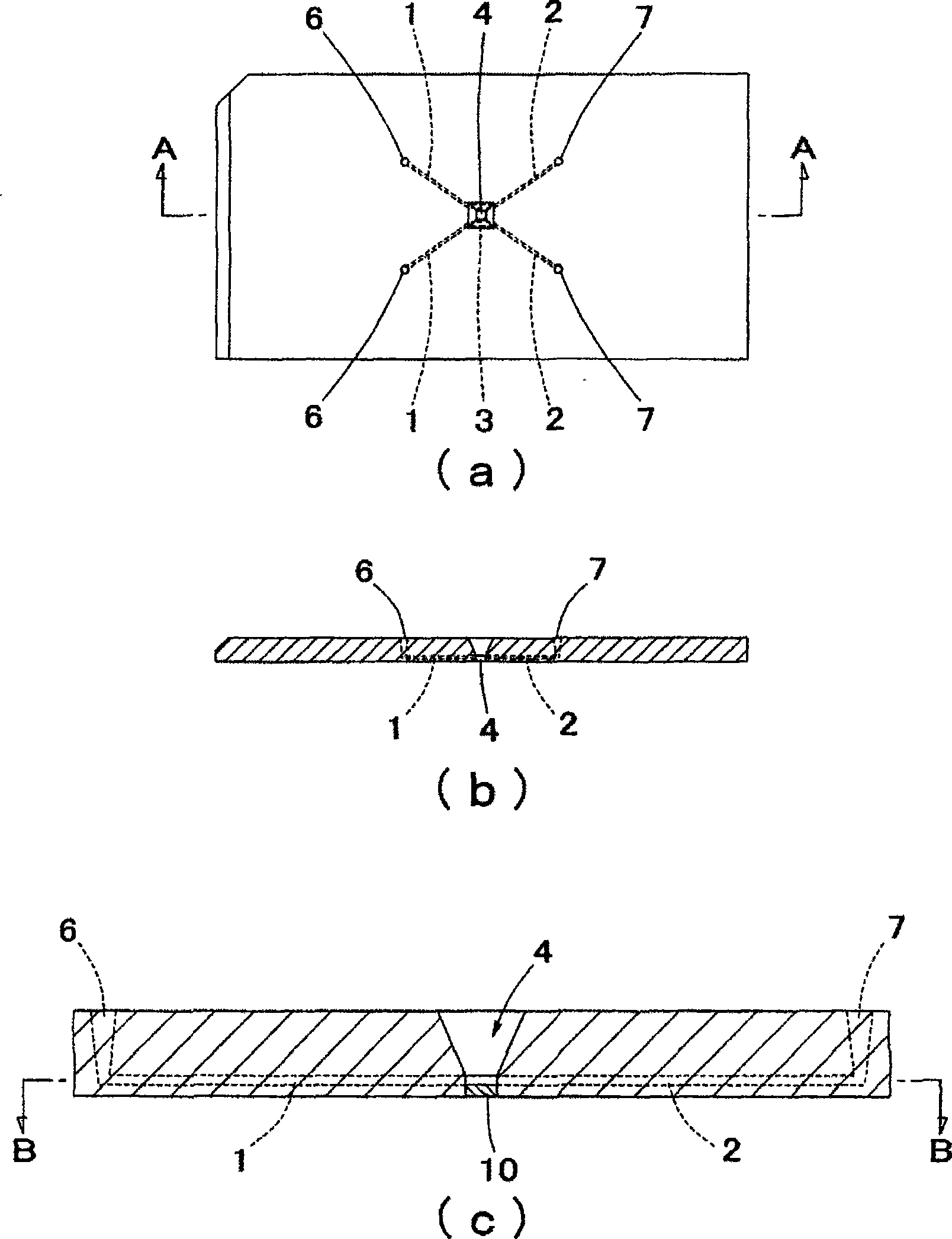
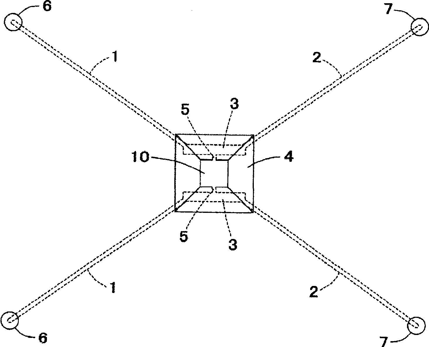
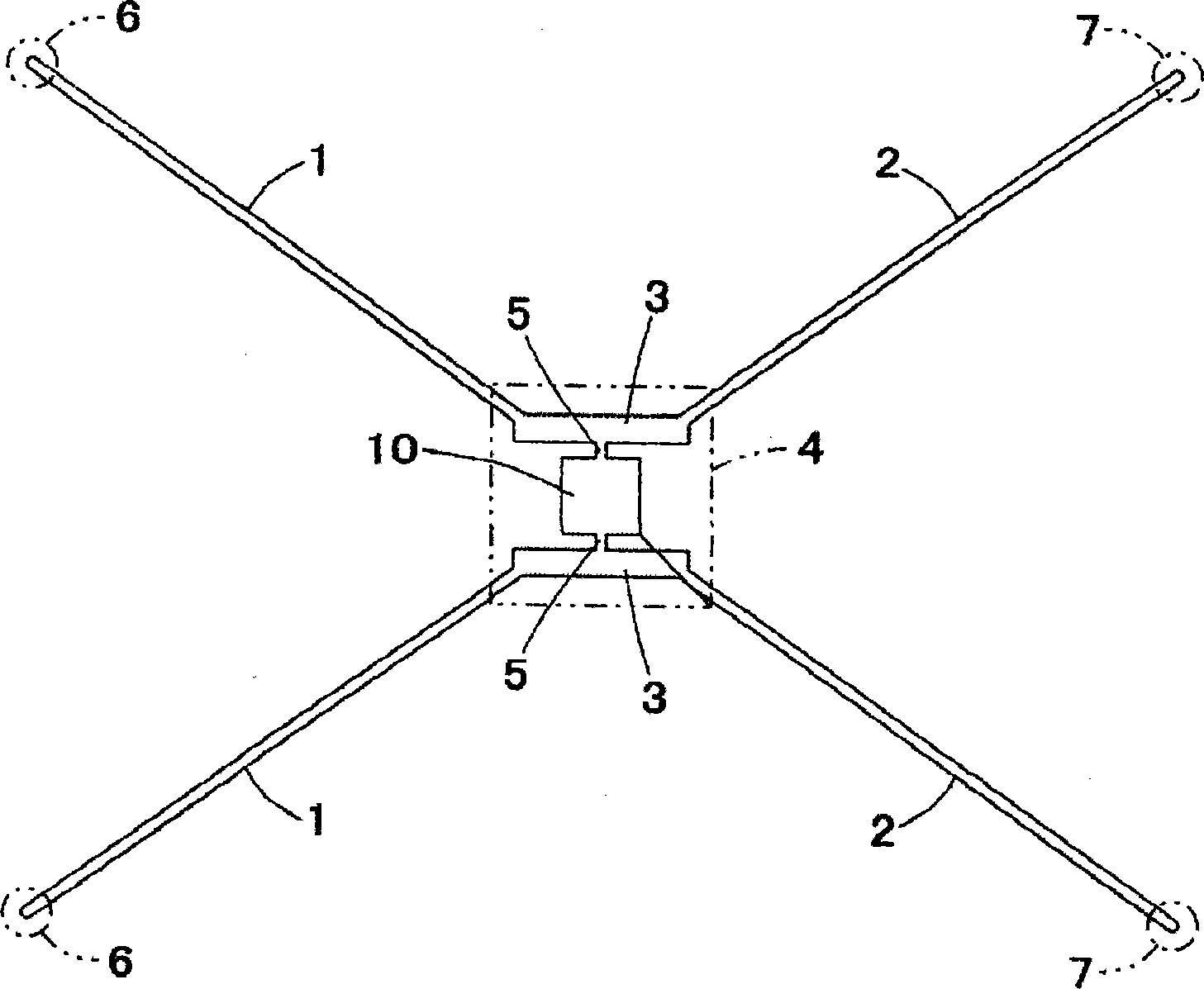
[0044] figure 1 shows a microchip for arranging cells according to the present invention (hereinafter simply referred to as: microchip); figure 1 (a) is a floor plan; figure 1 (b) is along figure 1 Sectional view of line A-A shown in (a); figure 1 (c) for figure 1 (b) Magnified view of the center. figure 2 for figure 1 Magnified view around the center of (a). image 3 for along figure 1 (c) Cross-sectional view along line B-B.

[0045] The microchip of the present invention includes a substantially planar substrate formed of a synthetic resin having light-transmitting properties such as a photocurable resin. The substrate includes at least one cell supply flow path 1 , at least one cell discharge flow path 2 , at least one storage portion 3 , at least one cell arrangement portion 4 and at least one connection flow path 5 .

[0046] The cell supply flow path 1 is used to transfer the cells transferred by the liquid from the supply mechanism to the storage part 3, the ...


PUM


Abstract

To provide a microchip for cell alignment whereby cells can be quickly and accurately transferred and aligned with the combined use of the advantages of a system using optical tweezers and another system using microchannels. A microchip for cell alignment which is provided, on a single baseboard, with: a cell injection channel which has a cell injection port connected to a liquid feeder mechanism and through which cells injected from the cell injection port migrate; a cell discharge channel which has a cell discharge port connected to a drainage mechanism and through which cells migrate toward the cell discharge port; a pooling part which is formed between the cell injection channel and the cell discharge channel and in which cells in the mid-course of flowing from the cell injection channel to the cell discharge channel are pooled; a cell alignment part into which the cells pooled in the pooling part are introduced; and a guiding branch for connecting the cell alignment part to the pooling part; wherein the cell alignment part has multiple cell storage areas separated from each other, and the pooling part has a width larger than those of the cell injection channel and the cell discharge channel while the guiding branch has a width smaller than that of the pooling part.

Description

technical field [0001] The present invention relates to a microchip and method for arraying cells, further, to a method for transferring cells using liquid flow together with optical clamps during arraying operations, and to a cell array for this method With a microchip. Background technique [0002] Optical clamp operation is known as a cell transfer method in a non-contact manner by capturing and scanning cells by using laser beam radiation pressure (for example, Patent Reference 1). [0003] This method preferably provides accurate and free cell transfer, however, it is not efficient due to the slow transfer rate, which results in taking a lot of time when transferring many cells or transferring over long distances. [0004] Another non-contact method of cell transfer is to send liquid to a microfluidic circuit with a micropump (eg, patent reference 2). [0005] The advantage of this method is that large numbers of cells can be quickly transferred at one time. However,...

Claims


Application Information

Patent Timeline
Patent Type & Authority Applications(China)
IPC IPC(8): C12M1/00C12N5/02
CPCG01N15/1484B01L3/502761C12M33/00G01N15/1056Y10T137/85938Y10T137/0318
Inventor 佐藤节哉山户俊幸林克明松本由多加落谷孝广王勇
Owner ABSIZE INC
Why Eureka
Try Eureka