RF external triggering gaseous discharging switch

A technology of gas discharge and gas discharge tube, which is applied in the direction of solid cathode components, etc., to achieve the effects of extremely long discharge time, low noise, and reduced manufacturing costs

Inactive Publication Date: 2011-08-17
东莞市新铂铼电子有限公司
View PDF1 Cites 0 Cited by
  • Summary
  • Abstract
  • Description
  • Claims
  • Application Information

AI Technical Summary

Problems solved by technology

The biggest disadvantages of this ball gap discharge method and its device are: high noise, large energy loss, and difficulty in regulating the ball gap discharge gap.
[0006]① Due to the two discharge gaps (anode-grid, grid-cathode), the power consumption is still too large. If the single gap voltage drop is 20V~30V, The voltage drop between the two gaps will double to 40V~60V, the power consumption will inevitably double, and the energy loss will be large
[0007]② Due to the large power consumption, the supporting auxiliary facilities are bound to increase, resulting in an increase in manufacturing costs
[0008]③ Since the hydrogen thyratron is filled with hydrogen gas, the conductivity of hydrogen gas is low (compared with argon gas, only a few tenths of that of argon gas), To maintain a certain conductivity, there must be a sufficiently large charge passing surface, and the volume of the entire hydrogen thyratron must be large enough, so that the miniaturization of the hydrogen thyratron and its switch encounters insurmountable obstacles, and it becomes a hydrogen thyratron and a hydrogen thyratron. The technical bottleneck of its switch miniaturization
[0009]④The anode and cathode of the hydrogen thyratron must be electrically connected to the positive and negative electrodes of the external circuit respectively, that is to say, the electrodes of the hydrogen thyratron have polarity For the difference, you can’t make a mistake when connecting with the circuit, which will bring inconvenience to the design and actual operation.
And above-mentioned ball gap discharge method and its switch, hydrogen thyratron method and hydrogen thyratron, all can not meet the requirement because of its own technical defect

Method used


Image

  • RF external triggering gaseous discharging switch
  • RF external triggering gaseous discharging switch
  • RF external triggering gaseous discharging switch

Examples


Embodiment Construction

[0035] Hereinafter, specific embodiments of the present invention will be described in conjunction with the accompanying drawings.

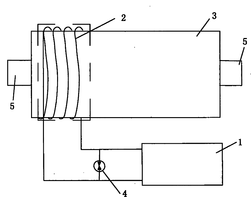
[0036] The radio frequency external trigger method of the gas discharge tube of the present invention adopts the radio frequency external trigger gas discharge tube, the radio frequency is generated by the radio frequency power supply, the radio frequency generated by the radio frequency power supply is coupled to the gas discharge tube through the load coil, and a radio frequency magnetic field is generated in the gas space in the gas discharge tube, so that The gas in the discharge tube is ionized, and the gas discharge tube changes from a non-conductive state to a conductive state.

[0037] Regarding the radio frequency external trigger method of the gas discharge tube, the frequency generated by the radio frequency power supply is above 1MHZ.

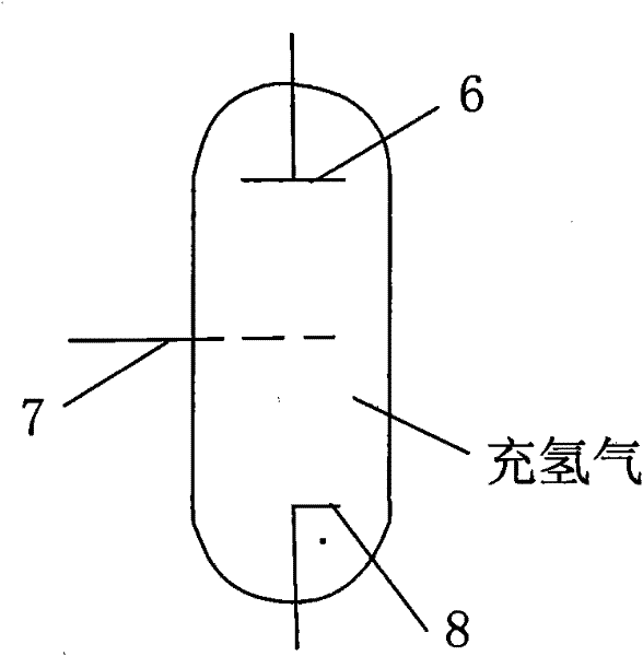
[0038] like figure 2 As shown, the structure of the radio frequency external trigger gas switch o...


PUM


Abstract

The invention relates to a method for radio frequency external triggering of a gas discharge tube and a radio frequency external triggering gas discharge switch, which relate to the technical field of gas charge switches. The method for the radio frequency external triggering of the gas discharge tube comprises the following steps that: a radio frequency external triggering gas discharge tube is adopted; and a radio frequency power supply generates radio frequency which is coupled to the gas discharge tube through a load coil, so that the gas in the discharge tube is ionized to make the gas discharge tube conducted. The radio frequency external triggering gas discharge switch comprises the gas discharge tube, the radio frequency power supply and the load coil, wherein the load coil is wound and fixed on the periphery of a metallized ceramic tube of the gas discharge tube, and the output end of the radio frequency power supply is connected with two ends of the load coil respectively. The method for the radio frequency external triggering of the gas discharge tube and the radio frequency external triggering gas discharge switch has the advantages of low noise, small energy consumption, large discharge current capability, low residual voltage, stable discharge, high reliability, easy automation control, and small volume, and can meet the needs of civil uses and military use.

Description

technical field [0001] The invention relates to a radio frequency external trigger method of a gas discharge tube and a gas discharge tube switch, more specifically, to a method for using radio frequency to externally trigger the electrical conduction of a gas discharge tube and a radio frequency external trigger gas discharge switch, which are widely used in shock Gas discharge switches in systems such as current wave generators, impulse voltage wave generators, accelerators, strong lasers, and radars. Background technique [0002] Impulse current wave generators or impulse voltage wave generators are very versatile. The switch is the main building block in the structure of impulse current wave generator or impulse voltage wave generator. Through the on and off of the switch, electric pulses are generated to form electromagnetic impact energy, even huge electromagnetic impact energy. [0003] In the prior art, there are mainly the following two methods and switches based...

Claims


Application Information

Patent Timeline
Patent Type & Authority Patents(China)
IPC IPC(8): H01J17/02
Inventor 曾献昌米本兴
Owner 东莞市新铂铼电子有限公司
Why Eureka
Try Eureka