
Horizontal omnidirectional planar printed antenna

A printing antenna and planar technology, which is applied in the direction of antenna, slot antenna, radiation element structure, etc., can solve difficult problems and achieve the effects of low out-of-roundness, compact antenna structure, and simplified antenna design

Inactive Publication Date: 2013-01-02
SICHUAN UNIV
View PDF0 Cites 1 Cited by
  • Summary
  • Abstract
  • Description
  • Claims
  • Application Information

AI Technical Summary

Problems solved by technology

The maximum gain is 6.1dBi in the working frequency band centered on 2.4GHz, and the out-of-roundness can only be controlled within 2dB; the paper "Analysis and simulation of cylindricalconformal omni-directional antenna" presented at the 2005 International Microwave Progress Conference Asia Pacific An omnidirectional antenna with a radiating element array built around a cylindrical substrate. This antenna is also derived from the basic common-ground antenna. However, the previous planar substrate was replaced by a cylindrical substrate, which achieved good simulation results. The actual Difficulty in processing

Method used


Image

  • Horizontal omnidirectional planar printed antenna
  • Horizontal omnidirectional planar printed antenna
  • Horizontal omnidirectional planar printed antenna

Examples


Embodiment

[0027] The structure of the horizontal omnidirectional planar printed antenna is as follows Figure 1~3 As shown, it includes slot array, printed circuit board, stripline transmission line feed network.

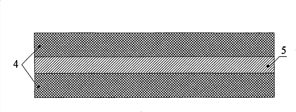
[0028] The stripline transmission line feed network is composed of metal ground layers 1, 3, feed layer 2, and dielectric layer 4, which realizes uniform feed and impedance matching of the antenna slot array, such as figure 1 shown. The feed layer 2 contains a metal conduction strip 5, such as figure 2 shown.

[0029] The slot array is composed of one or more sets of slot units 6. Taking 8 sets of slot units as an example, the slot units are printed on the upper and lower layers of metal layers 1 and 3 on the PCB, such as image 3 shown.

[0030] Through numerical simulation calculation and antenna test, the working frequency band of the horizontal omnidirectional planar printed antenna extends from 5.66GHz to 5.94GHz, and the bandwidth reaches 4.7%. At a working freque...


PUM


Abstract

The invention discloses a horizontal omnidirectional planar printed antenna which is characterized in that the planar printed antenna comprises three metal layers and two medium layers; the upper metal layer and the lower metal layer are metal stratums (1,3); the middle metal layer is a feeding layer (2); the center of the feeding layer is printed with a metal conduction band (5); the metal conduction band, the upper metal stratum and the lower metal stratum form a stripline transmission line; the upper and the lower metal stratums (1,3) are symmetrically manufactured with a plurality of rectangular rifts (6) along the direction of the metal conduction band; and a medium layer (4) is arranged between the metal stratums (1,3) and the feeding layer (2) respectively. The horizontal omnidirectional planar printed antenna has the advantages of high gain, good horizontal omnidirectional property, simple manufacture and low cost.

Description

technical field [0001] The invention relates to a horizontal omnidirectional planar printed antenna, which belongs to the field of antennas in radio equipment. Background technique [0002] As the transmitting and receiving equipment of radio communication, the antenna directly affects the quality of the radio signal. Therefore, the antenna occupies an extremely important position in radio communication. An antenna system with a reasonable structure and excellent performance can minimize the requirements on the entire wireless system, thereby saving system costs and improving the performance of the entire wireless system. [0003] With the development of modern wireless communication, many base station antennas need to communicate with communication terminals in all directions. Therefore, base station antennas are required to achieve 360-degree transmission or reception coverage in the horizontal plane, that is, the radiation pattern is omnidirectional in the horizontal plan...

Claims


Application Information

Patent Timeline
Patent Type & Authority Patents(China)
IPC IPC(8): H01Q13/08H01Q13/10H01Q1/38
Inventor 陈星黄卡玛刘长军郭庆功赵翔华伟闫丽萍杨晓庆
Owner SICHUAN UNIV
Learn More